
Heat pipe heat sink testing should establish whether a defined assembly meets its temperature requirements under agreed operating conditions. A useful acceptance report identifies the sample revision, heat input, cooling conditions, mounting method, sensor positions and decision rule. A temperature reading without those details cannot support a repeatable purchasing decision.
For OEM projects, begin with two separate questions: does the heat pipe perform as a component, and does the completed assembly cool the intended source? This guide focuses on the second question. It provides a practical framework for agreeing a prototype test with a supplier or laboratory, including a sensor map and an acceptance record.
1. Separate Heat Pipe Characterization from Assembly Acceptance
A heat pipe capacity test examines a particular pipe with defined heating and cooling lengths, temperature conditions and orientation. Its maximum transport capability cannot be transferred unchanged to another geometry or installation. Fraunhofer’s heat pipe characterization work illustrates why applied power, cooling conditions and inclination belong in the test definition.
An assembly test includes additional interfaces and components: the source contact, thermal interface material (TIM), base, pipe joints, fin stack and cooling environment. The acceptance question concerns the performance of that complete configuration.
| Test scope | What the result can establish | What remains outside the result |
|---|---|---|
| Individual heat pipe | Behavior under the stated component test conditions | Performance after forming, joining and installation |
| Heat sink assembly on a fixture | Performance with the specified heater, TIM, mounting and cooling | Unrepresented conditions in the final product |
| Assembly in the product | Temperatures under the tested workload and enclosure conditions | Untested workloads, orientations and service conditions |
Novark’s testing overview likewise distinguishes heat pipe function and capacity tests from thermal-module resistance measurements. Use this distinction when requesting evidence. A component certificate does not replace assembly results, and an assembly acceptance test does not need to search for a destructive maximum load.
2. Freeze the Configuration Before Applying Power
Assign a test-plan revision before samples arrive. Record which variables are fixed and which will change deliberately. A supplier’s open fixture and the customer’s enclosure may both provide useful data, but their results answer different questions.
| Controlled input | Record in the test plan |
|---|---|
| Sample | Part number, drawing revision, serial number and build differences |
| Heat source | Footprint, location, number of sources and applied load per source |
| Contact stack | TIM identity, application method, installed thickness or control method |
| Mounting | Fasteners, tightening sequence, specified torque or controlled force |
| Cooling | Inlet temperature, fan/control condition, flow measurement and enclosure revision |
| Orientation | Drawing axes, gravity direction and installed position |
| Instrumentation | Equipment IDs, ranges, calibration status and channel map |
| Acceptance | Temperature limits, required runs, uncertainty treatment and stop limits |
For a heater surrogate, document how it represents the actual device. Matching total watts while using a much larger contact patch can change the thermal problem. Celsia’s thermal test chip guide describes test sources designed to represent different heat-generation patterns. Identify which package features your fixture reproduces and which require later product testing.
For forced-air testing, specify the flow measurement location and method. Fan speed and free-air flow rating are not interchangeable with measured flow through the assembly. Keep the enclosure, grille, filter and bypass clearances controlled between comparable runs. For natural convection, record nearby obstructions and unintended drafts.
3. Define Sensor Positions on a Drawing
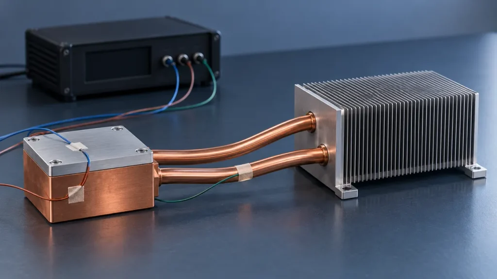
Use numbered channels tied to coordinates, photographs and an attachment method. “Base temperature” is insufficient if one team measures beside the source and another measures at the opposite corner.
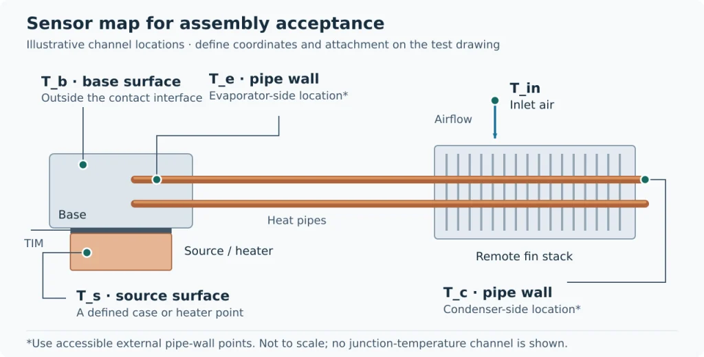
| Channel | Defined measurement | Main use |
|---|---|---|
| T_s | Specified source case or heater surface | Acceptance temperature, if the limit applies at this location |
| T_b | Specified accessible base surface | Local base-temperature diagnostic |
| T_e | Accessible evaporator-side pipe wall | Diagnostic trend near the heated region |
| T_c | Accessible condenser-side pipe wall | Diagnostic trend near the cooled region |
| T_in | Air entering the fin stack at a defined plane | Cooling boundary condition and reference temperature |
Position the inlet sensor to sample incoming air without touching metal or being dominated by the hot assembly. Where inlet temperature varies across the face, define multiple points and the averaging method. Record the actual arrangement rather than treating room temperature as inlet temperature.
Select sensors and attachment methods that suit the surface and expected range. Avoid casually trapping a thermocouple between mating faces: this can disturb contact and TIM thickness. An embedded probe, machined groove or modified sample requires an agreed method and a record of how it changes the part.
Thermocouple accuracy also depends on the measurement chain. NI’s cold-junction guidance explains how nearby heat sources can create terminal-temperature errors. Record sensor type, wire routing, attachment, logger configuration and relevant corrections.
T_s is not automatically semiconductor junction temperature. Junction acceptance requires a device-appropriate measurement or a justified correlation. Likewise, T_e minus T_c alone does not reveal the heat carried by an individual pipe in a multi-pipe assembly.
4. Report Power and Thermal Resistance on the Same Basis
Specify the thermal quantity before calculating it. For a steady-state test with a defined source-surface temperature and a justified net heat flow into the assembly:
R_s–in = (T_s − T_in) / Q_net, in °C/W.
This is an effective source-surface-to-inlet metric for that setup. It includes the interface and other elements between the chosen endpoints; it is not the heat pipe’s intrinsic resistance or junction-to-air resistance.
Measure heater power at the intended electrical boundary. For a steady DC resistive heater, measured voltage across the heater and current through it give P_heater = V × I. Power-supply setpoints alone are insufficient. For switched power, use a measurement method that captures average real power.
Some heater energy can leave through supports, wiring or exposed surfaces. If those paths are significant, establish and document a loss correction before claiming Q_net. If only electrical input is known, report the temperature rise and electrical power separately, or label their ratio explicitly as an apparent resistance based on electrical input.
For illustration only, a 30°C rise divided by 100 W electrical input gives 0.30°C/W on that electrical basis. If a separately justified loss assessment found 90 W entering the assembly, the corresponding net-heat ratio would be about 0.333°C/W. These assumed values explain reporting boundaries; they are not HJTC measurements.
For multiple sources, report each source’s power and temperature. One total-power ratio can conceal a local temperature-limit failure.
5. Agree the Run Matrix and Steady-State Rule
Choose runs from the product’s operating requirements. The following is a planning framework; the actual loads, temperatures, sample count and repetition count must be agreed for the project.
| Run | Purpose | Conditions to define |
|---|---|---|
| Nominal operation | Establish a reference result | Representative power, inlet and cooling |
| Limiting sustained condition | Check the demanding service condition | Relevant combination of load, inlet and cooling limits |
| Required orientation | Check installation sensitivity | Gravity direction and fixed cooling conditions |
| Startup or restart | Check the temperature transient | Initial temperature, load sequence and peak limit |
| Repeat or remount | Assess reproducibility of the setup | Repeat count and whether TIM/mounting is renewed |
Do not automatically combine unrelated extremes into a physically impossible operating point. Conversely, testing only one variable at a time can miss a demanding combination that is allowed in service. Document the rationale for each condition.
Before energizing the heater, agree temperature and equipment stop limits and the response to lost cooling or an invalid sensor. Bring the setup to the required initial condition, apply the defined load sequence and log time-aligned temperature, power and cooling data.
Define steady state using a stated observation window and allowable change or slope for the relevant temperature channels, together with limits on inlet, power and cooling variation. Select thresholds that the instrumentation can resolve and that suit the assembly’s response. A fixed elapsed time alone is not evidence of equilibrium.
Use the agreed stable window for reported averages and retain the full trace. If a channel never meets the criterion, report the run as incomplete or unstable. Startup peaks and time to reach a limit are separate transient results; averaging them away would answer the wrong question.
6. Distinguish Repeatability from Measurement Uncertainty
A second run without disturbing the setup checks a different issue from a second run after removing the sink, renewing the TIM and remounting it. Label these separately. Remount variation helps reveal sensitivity to the assembly procedure; it should not be hidden by averaging all runs into one favorable number.
An uncertainty assessment should address the reported quantity and the actual measurement method. Relevant contributors can include sensor calibration, logger behavior, attachment effects, electrical power measurement and any heat-loss correction. Correlations matter when subtracting temperatures or combining measurements, so do not assume every contribution is independent.
Keep observed setup variation visible alongside the uncertainty assessment and explain any statistical treatment. If the claimed improvement is similar to the unresolved measurement or remount variation, obtain better evidence before choosing a winner.
Agree the conformity rule before testing. NIST’s decision-rule definition connects conformity decisions with the treatment of measurement uncertainty. For example, a project could require a measured temperature plus a stated expanded uncertainty to remain below its upper limit. That is a possible agreed rule, not a universal heat sink requirement.
7. Build an Acceptance Record That Can Be Reviewed
Acceptance should refer to a defined configuration and a complete evidence set. Use the following record structure in the sample review; leave unresolved fields open until the parties agree them.
| Acceptance item | Required record |
|---|---|
| Configuration match | Sample ID, drawing revision, fixture and mounting records |
| Test validity | Actual power, inlet, cooling and steady-state evidence |
| Thermal requirements | Named channel, applicable limit, result and decision rule |
| Mechanical requirements | Required dimensions and inspection results |
| Exceptions | Deviations, failed or incomplete runs, and agreed disposition |
| Traceability | Raw-data files, sensor map, equipment IDs, date and reviewer |
Keep “pass,” “fail,” “incomplete” and “not tested” distinct. Missing inlet data or an unapproved change in source footprint can invalidate a comparison even when the displayed temperature is low. A revised sample should retain its own identity and any retest rationale.
Initial thermal acceptance, reliability qualification and production screening are separate activities. Celsia’s quality and testing page describes both validation and customer system testing, while its heat pipe QC overview discusses component and assembly checks. Those are descriptions of Celsia’s processes, not universal schedules or HJTC capabilities.
If cycling, vibration or other environmental exposure is required, agree the applicable method, severity and post-exposure thermal check separately. Do not infer service life from a single steady-state pass.
Frequently Asked Questions
Is a low temperature difference enough to approve a heat pipe heat sink?
No. The temperature difference needs defined measurement points, heat input and cooling conditions. Approval also depends on the project’s temperature limits, test validity and agreed decision rule.
How long should a thermal acceptance test run?
Long enough to satisfy the agreed stability criterion and capture any required transient. There is no single duration established here for every geometry, thermal mass and cooling arrangement.
Can a supplier fixture test replace testing in the final product?
A fixture test can support comparison and sample acceptance within its defined scope. Product testing is still needed for conditions the fixture does not represent, such as recirculation, nearby heat sources or workload-dependent cooling control.
Prepare a Test Brief for HJTC
HJTC’s heat sink product range lists heat pipe, extruded, skived and bonded-fin configurations. When discussing a sample, provide the source map, power profile, installation drawing, cooling conditions, target quantities and acceptance requirements together.
Contact HJTC to discuss the required configuration and supply scope. Before ordering, confirm who will perform each test, the available equipment and method, and which report will accompany the samples. This test-plan framework does not certify a particular part or imply that a listed test has already been performed.