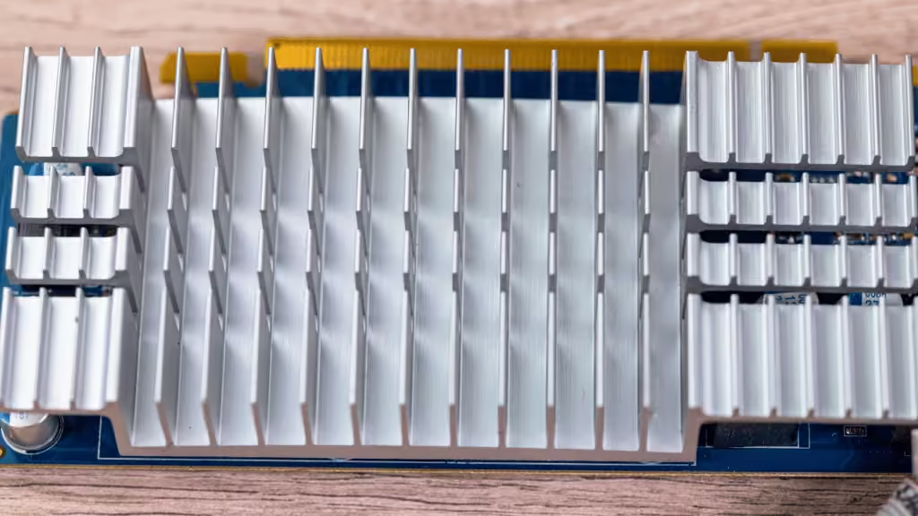
Thermal spreading resistance is the extra temperature penalty created when heat enters a base through a small area and spreads through a larger solid. A larger fin array can offer more cooling area, yet the component may remain hot if the base cannot carry heat effectively to that area.
For an OEM design review, define the source footprint, base geometry and cooling boundary before choosing a thicker plate, a copper insert or a two-phase spreader. This guide explains the resistance terms, works through a calculation with explicit assumptions, and compares practical ways to improve the heat path.
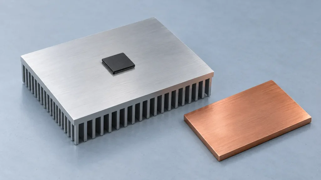
Define Spreading Resistance Before Comparing Numbers
Spreading resistance has units of K/W, equivalent to °C/W for temperature differences. The associated temperature rise is heat flow multiplied by resistance. A temperature difference in degrees alone is not a resistance value; it must be tied to a heat load.
For the idealized plate used later in this article, the reference temperature is the uniform temperature of its entire lower face. Define the base resistance using the area-averaged temperature of the source contact:
R_base = (T_source,mean − T_bottom) / Q
The plate resistance can be separated into a one-dimensional contribution and an additional spreading contribution:
R_base = R_1D + R_sp, where R_1D = t / (k × A_base).
Here, t is plate thickness, k is thermal conductivity and A_base is the full plate area. This decomposition follows the uniform-flow and multidimensional terms used in rectangular flux-channel analysis. It applies to the stated model; another calculator may use a different reference temperature or include additional terms.
Using the full base area in t/(kA) alone assumes heat is uniformly distributed across that area. It misses the nonuniform temperature field produced by a smaller source. Conversely, using only the source area describes a restricted one-dimensional column and does not account for lateral conduction through the surrounding plate.
Check whether a reported result uses a peak temperature or an area average. These quantities are different even for a uniformly heated footprint. Neither should be substituted for semiconductor junction temperature without accounting for the package and interfaces.
Distinguish Base Spreading from Contact and Cooling Problems
A high component temperature can result from poor contact, inadequate heat spreading or insufficient heat rejection. The remedies differ, so record temperatures and boundary conditions before changing the structure.
| Observation | Possible explanation | Useful follow-up |
|---|---|---|
| Large temperature change across the component-to-base interface | TIM thickness, contact coverage or mounting condition | Check the assembled interface and defined temperature locations |
| Strong temperature variation across the base | Concentrated heat input, limited lateral conduction or uneven cooling | Compare the source map with the cooling map and a conduction model |
| Most of the sink is hot relative to inlet air or coolant | Heat rejection may be limiting | Check actual flow, inlet conditions and heat exchanger performance |
These observations help form a hypothesis; none proves a single cause. A shiny metal surface can also mislead an infrared measurement unless emissivity and reflected temperature are addressed. Surface measurements should be compared at known locations under a repeatable load.
ATS illustrates how a small source can create a temperature gradient across a larger heat sink base. Use that pattern as a reason to investigate spreading, while also checking the interfaces and cooling distribution.
HJTC’s high heat flux cooling guide covers the wider heat path. The narrower question here is how much of the temperature rise belongs to the base and whether a different spreading structure can reduce it.
Define the Geometry and Cooling Boundary
Record the dimensions of the actual heat input area. A package outline, die area and mechanical contact footprint may differ. If power is unevenly distributed, identify the active regions rather than applying total power uniformly over an unrelated outline.
The model also needs the source position. A centered source has access to surrounding material on all sides; an offset source has a different path to the edges and cooled regions. Multiple devices require their simultaneous loads and locations. A single-source estimate cannot capture their mutual temperature effects.
Provide the base length, width and thickness, including pockets, inserts or local thickness changes. Use conductivity for the specified material and relevant temperature range. Treat the conductivities in the worked example below as selected calculation inputs, not guaranteed properties of every aluminum or copper grade.
Describe where heat leaves. Uniform cooling over the whole opposite face, cooling through discrete fin roots and cooling only at edge rails are different boundary conditions. An isothermal surface holds a prescribed temperature everywhere; a convective boundary relates local heat flux to a fluid temperature and heat transfer coefficient. They should not be exchanged without revising the model.
Keep the component-to-base interface and any base-to-cooler joint visible in the thermal model. If a supplier provides an assembly resistance that already includes base spreading, adding a second spreading term would count the same temperature rise twice.
Worked Example with an Isothermal Lower Face
The following calculation isolates conduction through a solid plate. It is an illustrative model, not an HJTC test, product rating or prediction for a complete heat sink. The entire lower face is held at 40°C, which is an idealized cooling condition and is not equivalent to specifying 40°C inlet air or coolant.
| Model input | Assumption |
|---|---|
| Plate dimensions | 60 × 60 × 4 mm |
| Heat input | 80 W, uniformly applied to one centered square footprint |
| Source footprints | 10 × 10 mm and 20 × 20 mm, evaluated separately |
| Solid conductivity | Constant, isotropic k = 200 or 400 W/m·K |
| Lower surface | Entire face fixed at 40°C |
| Other boundaries | Side faces and unheated upper surface insulated |
| Exclusions | Package, TIM, contact resistance, fins, convection and radiation |
| Reported temperature | Area average of the heated surface, not peak or junction temperature |
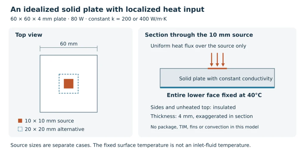
A cosine-series solution of the steady three-dimensional conduction equation was evaluated for these conditions. The calculation uses modes 0–800 in each in-plane direction. Increasing the cutoff from 400 to 800 changes the calculated base resistance by less than 0.005% for these cases. This checks numerical convergence, not agreement with hardware.
| Assumed k in W/m·K | Source in mm | R_sp in K/W | R_base in K/W |
|---|---|---|---|
| 200 | 10 × 10 | 0.1220 | 0.1276 |
| 200 | 20 × 20 | 0.0344 | 0.0400 |
| 400 | 10 × 10 | 0.0610 | 0.0638 |
| 400 | 20 × 20 | 0.0172 | 0.0200 |
For the first case, the uniform-flow contribution is:
R_1D = 0.004 / (200 × 0.060 × 0.060) = 0.00556 K/W.
Adding the spreading term gives approximately 0.1276 K/W. At 80 W, the mean heated-surface temperature is approximately 40 + 80 × 0.1276 = 50.2°C. Using only the full-area one-dimensional term would predict approximately 40.4°C and miss most of this model’s plate temperature rise.
For k = 200 W/m·K, increasing the source footprint to 20 × 20 mm reduces the calculated mean heated-surface temperature to about 43.2°C. This comparison changes how heat enters the plate. It does not show that adding an interface sheet to an unchanged device automatically creates the larger effective footprint; that additional spreading path and its contacts would need their own model.
Doubling k halves both resistance terms in this particular constant-property, prescribed-temperature problem. It does not establish a 50% improvement in a complete assembly, where interfaces and heat rejection remain. The example also makes no numerical claim for copper inserts, heat pipes or vapor chambers, which require different constructions and models.
Compare Practical Ways to Improve Heat Spreading
Compare candidates at the same source loads, temperature limits, installation envelope and cooling conditions. If a design changes any of those conditions, make the change explicit so its benefit can be understood.
| Option | When to evaluate it | Main comparison requirement |
|---|---|---|
| Adjust a solid aluminum base | A modest geometry change may provide an adequate path | Recalculate base conduction together with the available fin height and cooling area |
| Use a solid copper base | The solid conduction path is limiting and mass is acceptable | Compare the specified grade, geometry, mass and interfaces |
| Add a copper insert | Higher conductivity is needed near a localized source | Model insert dimensions, the surrounding base and the insert-to-base joint |
| Integrate heat pipes | Heat needs to reach underused or more remote cooling regions | Confirm source coupling, pipe routing, joining and operating limits |
| Use a vapor chamber | Heat needs to spread over a broad planar footprint | Confirm the specific construction, source and cooled areas, contact conditions and operating range |
A thicker base can improve lateral heat distribution in some assemblies, but it also changes the conduction distance and may reduce fin height inside a fixed envelope. ATS’s optimization example shows why the base and fin contribution must be evaluated together. Its preferred thickness belongs to that example, not to every heat sink. The isothermal-face calculation above is not a thickness optimization for an air-cooled extrusion.
A copper insert should not be modeled as though the entire base has become copper. Heat still crosses the surrounding material and any joint. An insert with an uncharacterized interface can give a very different result from a perfectly bonded model.
Heat pipes and vapor chambers offer additional transport paths, but their performance depends on the proposed device and integration. ACT describes vapor chambers as planar devices for spreading concentrated heat over a larger cooled area. That supports evaluating the architecture; it does not supply a universal resistance for a new design.
Celsia’s comparison calculator explicitly fixes several vapor chamber construction variables. When using a screening tool, record its assumptions and confirm whether they match the proposed part. A large effective conductivity number alone is insufficient to qualify a two-phase assembly.
Turn the Comparison into a Supplier Review
Prepare a baseline drawing and one comparison sheet for each candidate. Include source dimensions and coordinates, simultaneous powers, temperature limits, available base thickness, mass constraints and cooling conditions. Identify which interfaces and joining layers are included in the predicted result.
Ask for the reported temperature definition and reference location. A useful comparison states whether the result is calculated or measured, which model or sample revision it represents, and which assumptions remain open. Request both the source temperatures and enough spatial information to understand whether the spreading pattern changed.
A physical comparison should retain the agreed power, mounting condition, TIM and cooling setup. If a new base changes the airflow passage or contact stack, record that change rather than attributing the whole temperature difference to material conductivity.
HJTC’s published heat sink options include extruded, skived, bonded-fin and heat pipe configurations. Share the baseline and candidate requirements for a supply-option review, and confirm the proposed construction and supporting evidence for the project.
Send your heat-source map and drawings to HJTC, along with prototype quantity, expected production volume and the required decision date.
Frequently Asked Questions
Is Thermal Spreading Resistance the Same as Contact Resistance
No. Spreading resistance describes a nonuniform conduction field within a body. Contact resistance concerns heat transfer across an interface. Both can affect the same assembly, so an improvement to one may leave the other as the main limitation.
Does a Larger Heat Sink Always Reduce Source Temperature
No. Additional area helps only to the extent that heat reaches it and the cooling conditions use it effectively. Compare the source-to-reference temperature rise of the actual geometry rather than selecting by total fin area alone.
Can I Calculate Spreading Resistance with Thickness Divided by Conductivity and Area
That expression represents one-dimensional conduction under its assumptions. A localized heat source generally requires a multidimensional solution or an appropriate correlation with defined geometry and boundary conditions. Check whether a calculator reports spreading alone or a combined resistance.
When Should I Consider a Vapor Chamber
Consider it when planar heat spreading remains a meaningful limitation after reviewing the solid base and interfaces. Compare the proposed chamber with the baseline under the same project conditions, including contact geometry, installation orientation and cooling area. There is no single wattage or temperature-rise threshold that approves every design.