

Liquid cold plates can remove a large amount of heat from electronic systems. Yet an engineer can still see an unacceptable junction temperature even when coolant temperature, flow rate, and total cooling capacity appear adequate.
That does not necessarily mean the liquid loop is undersized.
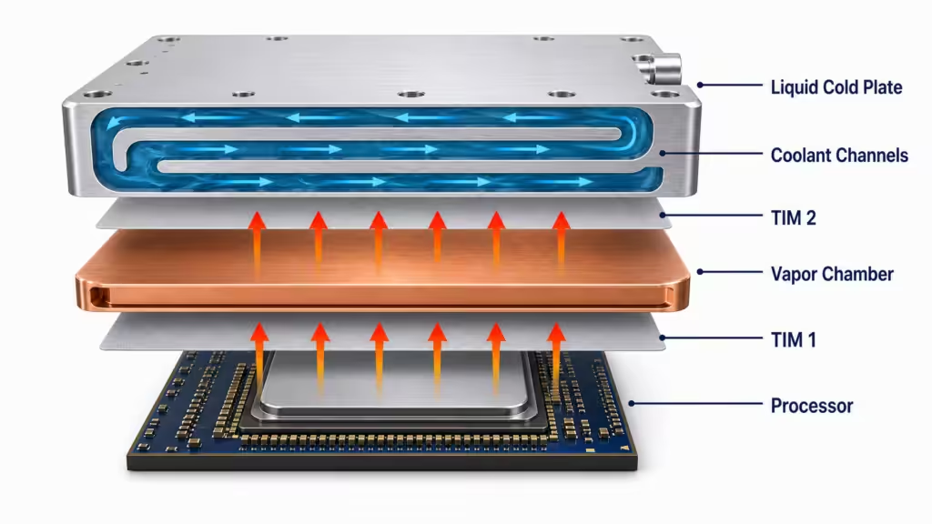
In many high heat flux cooling systems, the bottleneck sits before heat reaches the coolant. Heat must leave the package, cross a thermal interface material, spread through a base or two-phase heat spreader, and only then enter the cold plate channels. A high resistance at any one of those steps can keep the semiconductor hot while the coolant remains well within its expected operating range.
The practical lesson is simple: a cold plate cannot compensate for a poorly controlled interface. Neither can a high-conductivity TIM compensate for excessive bond-line thickness, weak contact pressure, surface warpage, material migration, or an inadequate spreading structure.
This guide explains how to diagnose the full junction-to-coolant path, when to modify the cold plate, where thermal interface materials fit, when vapor chambers or heat pipes help, and what engineers should validate before releasing a design to production.
The short answer
A cold plate is designed to carry heat into a moving coolant. It performs that function only after heat has reached the plate.
When the source is small and power is concentrated, three upstream resistances can become decisive:
- Package and contact resistance between the semiconductor assembly and the cooling structure.
- TIM resistance created by the material, its bond-line thickness, contact quality, and aging behavior.
- Spreading resistance as heat expands from a small source footprint into a larger cold-plate area.
Vapor chambers can spread heat before it reaches the cold plate. Heat pipes can transport heat to a remote cooling location. Thermal interface materials fill microscopic or macroscopic gaps at the solid-to-solid interfaces connecting those devices.
These technologies solve different parts of the same thermal path. They should be designed together, not selected independently.
How liquid cold plates work
A liquid cold plate usually consists of a thermally conductive base with internal coolant channels. The heat source is mechanically coupled to the plate, while a pump moves water-glycol, dielectric fluid, or another specified coolant through the channels. Heat conducts through the solid structure and then transfers into the moving liquid.
Cold plates are attractive because they can:
- remove more total heat than practical air cooling in many compact systems;
- carry heat to a remote radiator or facility water loop;
- reduce dependence on chassis airflow;
- support dense groups of CPUs, GPUs, power modules, memory, storage, and voltage-regulation components;
- provide repeatable cooling when flow, pressure drop, coolant chemistry, and inlet temperature are controlled.
The NREL Best Practices Guide for Energy-Efficient Data Center Design classifies cold plates and immersion systems as direct-liquid-cooling approaches and notes their adoption in high-performance computing environments. Intel server documentation also shows that liquid-cooled platforms still use multiple TIM forms at processor, GPU, memory, voltage-regulator, and transfer-plate interfaces. In other words, liquid cooling does not remove the need for interface engineering; it increases its importance.
Hongjitc’s liquid cold plate solutions cover microchannel, battery, power-electronics, IGBT/MOSFET, server, and custom aluminum architectures. The final design still has to match the source map, flow target, pressure-drop limit, available material, joining process, and production volume.
Why a cold plate can reach a thermal limit
The temperature rise from the heat source to the coolant can be represented with a simplified resistance network:
Rθ,junction-to-coolant = Rθ,package + Rθ,TIM + Rθ,spreading/base + Rθ,convection
For a steady-state heat load:
ΔT = Q × Rθ,total
where Q is heat flow in watts and Rθ,total is the combined thermal resistance in kelvins per watt.
This model is deliberately simple. A real assembly may include an integrated heat spreader, solder or sintered layer, lid, TIM, vapor chamber, mounting plate, second TIM, cold-plate base, and coolant-side film resistance. It may also contain several heat sources that interact thermally.
Still, the model reveals why increasing coolant flow does not always solve a hotspot. Flow can improve the coolant-side part of the path, but it does not automatically reduce contact resistance, TIM thickness, or lateral spreading resistance upstream of the channels.

1. The source footprint is smaller than the useful cold-plate area
A small die or power module may inject heat into only a fraction of the cold plate. The heat must spread laterally before the full cold-plate area and channel network can be used effectively.
If the base is too thin, the material has insufficient in-plane conductance, or the nearest effective coolant boundary is too far from the hotspot, a steep local temperature gradient can develop. A thicker copper base may improve spreading, but it also adds mass and may conflict with z-height or weight targets.
This is the design space where a vapor chamber may help. Instead of relying only on solid conduction, the sealed two-phase structure evaporates and condenses a working fluid to redistribute heat over a larger area.
2. The interface is not as thin or uniform as the model assumes
Even surfaces that look smooth contain microscopic peaks and valleys. Flatness error, roughness, package bow, cold-plate warpage, and assembly tolerance can reduce real contact area.
A TIM replaces insulating air and conforms to those irregularities. But the TIM also becomes part of the thermal resistance network. If it is much thicker than required, poorly compressed, incompletely dispensed, contaminated, or unevenly distributed, its resistance may erase the benefit of a well-designed cold plate.
This is why thermal conductivity alone is an incomplete selection criterion. Engineers also need to evaluate:
- thermal impedance at the intended thickness and pressure;
- minimum achievable bond-line thickness;
- surface wetting and conformity;
- clamp-load distribution;
- pump-out, dry-out, bleed, or migration under cycling;
- electrical insulation and substrate compatibility;
- process repeatability in production.
3. The interface degrades during operation
High heat flux systems often experience fast and uneven temperature changes. The package, TIM, spreader, fasteners, and cold plate expand at different rates. Repeated movement can redistribute a non-curing compound, relax a pad, open edge voids, or change contact pressure.
A material that performs well in an initial bench test may therefore behave differently after hundreds or thousands of power cycles. The correct question is not only, “What is the day-one thermal resistance?” It is also, “Does the interface remain continuous at the required pressure, temperature, orientation, and duty cycle?”
Why localized hotspots are difficult to cool
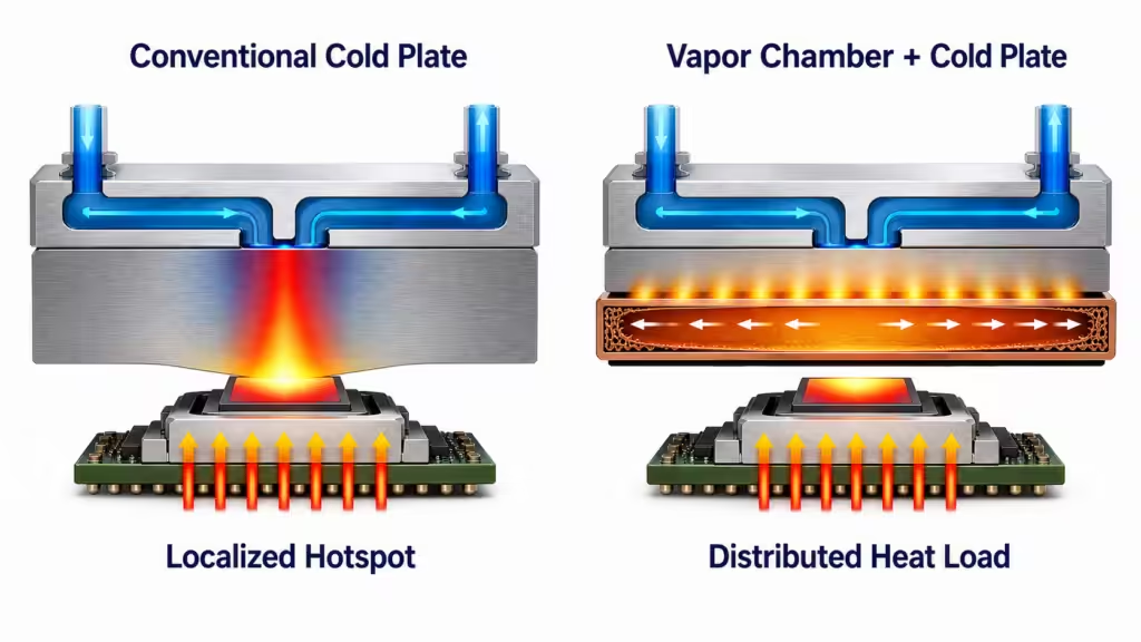
High total power and high heat flux are related, but they are not the same problem.
A large board can dissipate substantial power over a broad area without creating the same local temperature gradient as a much smaller source. Conversely, one concentrated accelerator die, RF device, SiC module, or densely packaged control processor can challenge the local thermal path even when total system power remains within the coolant loop’s capacity.
The difficulty increases when the system also has:
- a sealed enclosure with little or no airflow;
- limited z-height above the package;
- several heat sources sharing one cold plate;
- nonuniform source heights and tolerance stack-up;
- shock and vibration requirements;
- electrical-isolation requirements;
- serviceability or rework constraints;
- strict weight and pressure-drop limits.
There is no universal heat-flux value at which every cold plate begins to struggle. The result depends on source size, channel location, base thickness and material, coolant conditions, interface construction, boundary conditions, and the allowed junction temperature. A threshold taken from another system should not be used as a design rule without checking those conditions.
What vapor chambers and heat pipes solve
Vapor chambers and heat pipes are sealed two-phase devices. Heat evaporates a working fluid at the hot region; vapor moves toward a cooler region; condensation releases the heat; and the liquid returns through a wick or gravity-assisted path, depending on the design. NASA and JPL describe heat-pipe systems as using two-phase working-fluid behavior, vapor pressure, and capillary forces to transport heat without a conventional mechanical pump at the device level.
Their roles are related but different:
- A vapor chamber primarily spreads heat. It is useful when a small hotspot must be expanded into a larger condenser or cold-plate area.
- A heat pipe primarily transports heat. It is useful when the heat source and the available cold plate or heat-rejection surface are separated by chassis geometry.
- A thermosyphon uses phase change with gravity-assisted return. Orientation and system design therefore matter.
These devices can reduce the spreading or transport portion of the thermal path. They do not eliminate solid-to-solid interfaces. The evaporator must still receive heat from the package, and the condenser must still transfer heat into a cold plate, chassis, or heat sink.
That means the TIM remains important on one or both sides of the two-phase device.
The TIM is part of the cooling system, not an accessory
The purpose of a thermal interface material is not to “add cooling.” It is to reduce the resistance created when two real surfaces meet.
At a high heat flux interface, the best material is the one that produces the lowest stable interface resistance under the actual assembly conditions. That choice may not be the product with the highest datasheet conductivity.
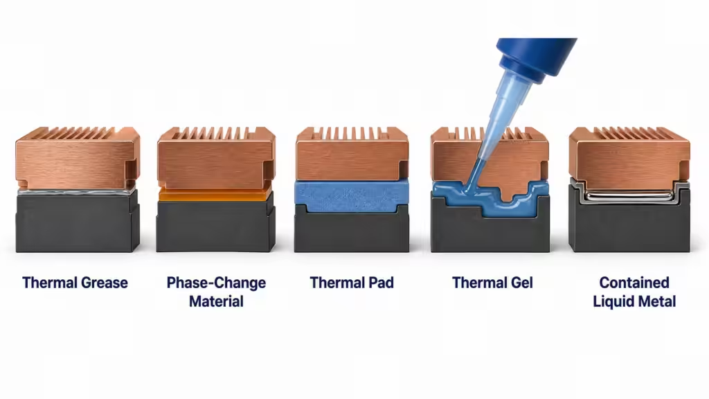
Common TIM options for cold-plate systems
| TIM type | Best fit | Main advantages | Main design concerns |
|---|---|---|---|
| Thermal grease or paste | Flat, tightly clamped surfaces requiring a thin bond line | Good wetting; low initial interface resistance; reworkable | Dispense control, contamination, pump-out, dry-out and long-term migration |
| Phase-change material (PCM) | Controlled, relatively thin interfaces that can reach the activation temperature | Solid handling before assembly; wets the surface after activation; controlled coverage | Activation behavior, edge flow, cycling stability, pressure and rework process |
| Soft thermal pad | Defined gaps, electrical insulation, mechanical tolerance or clean assembly | Preformed thickness; clean placement; easy inspection and rework | Compression pressure, thickness-related resistance, stress on components and compression set |
| Thermal gel or putty | Irregular or variable gaps and low-stress component-to-plate interfaces | Conforms to complex topography; useful across mixed component heights | Dispense volume, slump, voids, cure/no-cure behavior and long-term stability |
| Liquid metal | Extremely thin, tightly controlled interfaces with compatible materials | Very low interface resistance potential | Electrical conductivity, leakage containment, corrosion, substrate/plating compatibility and process risk |
For available material categories, see Hongjitc’s thermal materials section. Advanced applications should be validated against the actual interface rather than selected from conductivity alone.
Five parameters that matter more than a conductivity headline
For a broader system comparison before narrowing the cold-plate interface, start with Hongjitc’s guide to heat sinks and cooling methods.
1. Thermal impedance under the intended test condition
Thermal impedance includes the resistance of the material layer and its interfaces under a defined condition. It is more useful than bulk conductivity when comparing complete interfaces, but only when pressure, temperature, sample thickness, surface finish, and test method are known.
ASTM D5470-17(2024) covers steady-state thermal impedance measurements for materials that include greases, pastes, phase-change materials, gels, elastomers, and rigid specimens. ASTM also warns that the idealized test heat flow does not directly reproduce most practical applications. Datasheet testing is therefore a screening tool, not a substitute for assembly-level validation.
2. Bond-line thickness
For a uniform material layer, resistance generally increases with thickness. A high-conductivity material applied too thickly can perform worse than a lower-conductivity material applied in a thin, well-controlled layer.
The target thickness must account for:
- surface roughness and flatness;
- part-height tolerance;
- package bow and cold-plate warpage;
- particle size and minimum practical thickness;
- required electrical isolation;
- clamp pressure and component stress.
The correct target is not “as thin as possible” in isolation. It is the thinnest reliable layer that fills the required gap without starving the interface or overstressing the assembly.
3. Contact pressure
Pressure changes real contact area and material thickness. It may lower interface resistance, but excessive pressure can bend a PCB, overload a package, deform a vapor chamber, squeeze out a compound, or relax the interface after cycling.
Pressure should be treated as a design input. Engineers should define the fastener pattern, spring or retention system, allowed package load, plate stiffness, and pressure distribution rather than quoting only a total clamp force.
4. Surface and substrate compatibility
TIM performance depends on the surfaces it contacts. Aluminum, copper, nickel plating, coatings, polymer films, ceramics, and package lids do not have identical wetting, chemical, corrosion, or adhesion behavior.
Liquid metal requires especially strict compatibility and containment controls. It should not be used against aluminum or near exposed electronics without a verified material, plating, sealing, and process-control plan.
5. Aging under the real duty cycle
A steady laboratory test cannot reproduce every combination of power cycling, vibration, humidity, dwell time, orientation, and maintenance interval. Screening should therefore be followed by a test that represents the intended assembly and workload.
For a high heat flux processor, that may include repeated transitions between idle and full load. For automotive or industrial power electronics, it may also include vibration, thermal shock, electrical insulation, and long high-temperature dwell periods.
Pairing TIMs, two-phase spreaders, and cold plates
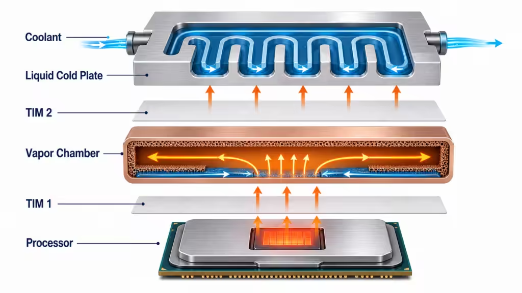
A common high heat flux architecture can include the following layers:
- semiconductor package or integrated heat spreader;
- first thermal interface material;
- vapor chamber or heat pipe evaporator;
- second thermal interface material, attachment layer, or integrated joint;
- liquid cold plate;
- moving coolant and the downstream heat-rejection loop.
Every extra layer adds another interface and another opportunity for thickness variation. A vapor chamber can improve lateral spreading, but its benefit can be limited if one of the adjoining TIM layers is too thick or poorly loaded.
The two interfaces may also require different materials. The package side may need an ultra-thin grease or PCM. The cold-plate side may need a compliant pad or gel to accommodate a wider tolerance. Treating both interfaces as identical can simplify purchasing while degrading thermal or mechanical performance.
Architecture A: Package → TIM → cold plate
Use this when the source footprint, cold-plate base, and channel geometry can meet the junction-temperature target without a separate spreader. Keep the TIM thin and uniform, and validate clamp pressure and cycling.
Architecture B: Package → TIM → vapor chamber → TIM → cold plate
Use this when localized spreading is the major bottleneck. Optimize the first interface for the source and the second for the larger condenser area. Check vapor-chamber flatness and pressure limits.
Architecture C: Package → TIM → heat pipe → remote cold plate
Use this when the cold plate cannot sit directly above the source. Check bend geometry, orientation limits, attachment method, and both evaporator- and condenser-side interfaces.
Architecture D: Multi-component board → pads/gels → conduction plate → cold plate
Use this when processors, memory, regulators, storage, and other components have different heights. Intel’s liquid-cooled server specifications provide a real example of a platform using grease and several gap-filler or pad locations within one liquid-cooling assembly. The material choice changes with the interface, even though the system shares the same coolant loop.
Cold plate design and manufacturing controls that matter
Improving a high heat flux system is not limited to adding a vapor chamber or changing the TIM. The cold plate itself has several interacting design variables.
Channel coverage and base thickness
Channels must pass close enough to the active source area to collect heat without leaving a long solid-conduction path. A thinner base can reduce the distance to the coolant, but it may also reduce lateral spreading, stiffness, flatness control, and pressure capacity. A thicker base can spread heat and resist deformation, but it adds conduction distance, mass, and material cost.
The correct thickness comes from the source map, channel layout, plate material, clamping load, internal pressure, and manufacturing process—not from one general rule.
Flow distribution and pressure drop
Increasing flow can improve the coolant-side heat-transfer coefficient, but it also raises pump demand and pressure drop. In a multi-source or parallel-channel plate, poor distribution can send too much coolant through one branch and too little through the hottest branch.
Engineers should compare temperature uniformity and pressure drop together. A channel pattern that produces an impressive local coefficient but cannot be pumped, cleaned, or manufactured reliably is not a finished design.
Joining process and material compatibility
Machined cover plates, vacuum brazing, friction stir welding, laser welding, and other joining methods create different limits for channel geometry, flatness, alloy choice, distortion, corrosion control, tooling, inspection, and production volume.
Hongjitc’s heat sink design guide explains the wider relationship between thermal design and production process. For a cold plate, the selected joining route must produce a continuous flow path and a stable external interface without creating distortion that increases TIM thickness.
Leak integrity, cleanliness, and long-term reliability
A cold plate must do more than pass an initial thermal test. The manufacturing plan should define proof pressure, leak-detection method, pressure cycling, coolant compatibility, corrosion testing, cleanliness, internal debris control, flatness, and traceability.
Those controls become especially important for microchannels, where contamination can block a small passage, and for electronics near high-value processors or power modules, where one leak can create a system-level failure.
Decide which part of the thermal path to change first
| Observed symptom | Likely bottleneck to investigate | First design action |
|---|---|---|
| Coolant inlet and outlet temperatures are acceptable, but one junction is too hot | TIM contact, local spreading, channel distance, package resistance | Map temperatures across the package, interface, plate surface, and nearest channel region |
| The entire plate and coolant outlet run too hot | Total coolant capacity, flow, radiator/CDU capacity, channel-side convection | Recheck total heat load, coolant rise, pump operating point, and downstream heat rejection |
| Parallel devices show uneven temperature | Flow maldistribution, source-to-channel mismatch, gap or clamp variation | Compare branch flow, pressure distribution, interface thickness, and channel coverage |
| More flow gives little temperature improvement | Upstream spreading or interface resistance | Test a revised base/spreader/interface before specifying a larger pump |
| Prototype passes, but production units vary | Flatness, joining distortion, TIM application, torque, contamination, process variation | Measure critical dimensions and process capability; lock assembly and inspection controls |
| Leak or pressure loss appears after cycling | Joint design, weld/braze quality, corrosion, fatigue, fitting load | Run leak localization, section analysis, pressure cycling, and material-compatibility review |
A practical development workflow
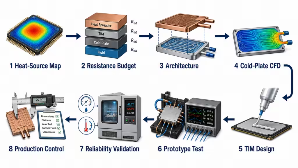
Step 1: Define the thermal and hydraulic targets
Record source power, footprint, source map, maximum junction or case temperature, coolant inlet range, flow and pressure-drop limits, ambient conditions, and the available temperature budget. Separate total heat load from local heat flux.
Step 2: Build the junction-to-coolant resistance budget
List each layer from junction to coolant. Estimate or measure the package, interface, spreader/base, and coolant-side contributions. Mark which values are measured and which are assumptions.
Step 3: Choose the cooling architecture
Decide whether the source can connect directly to a cold plate or whether it needs a vapor chamber, heat pipe, conduction plate, or hybrid air/liquid structure. Consider source size, transport distance, orientation, z-height, weight, service access, and reliability.
Step 4: Design the cold plate for performance and manufacturability
Develop channel coverage, base thickness, inlet/outlet location, branch balance, material, joining route, mounting features, flatness, corrosion protection, and inspection access together. Use CFD as a decision aid, then confirm the model with physical testing.
Step 5: Design the solid interfaces
Collect surface material, finish, flatness, roughness, nominal gap, tolerance, warpage, clamp pattern, and allowable pressure. Select grease, PCM, pad, gel/putty, liquid metal, or another joint only after those conditions are defined.
Step 6: Prototype and instrument the full system
Measure junction or case temperature, plate surface temperature, coolant inlet/outlet temperature, flow, and pressure drop. Use thermal imaging or embedded sensors to identify nonuniform contact, local hotspots, and flow imbalance.
Step 7: Validate reliability
Apply relevant proof pressure, leak testing, pressure cycling, power cycling, thermal cycling, vibration, humidity, corrosion, and dwell conditions. Inspect the flow path, joints, TIM, flatness, fittings, and surfaces after testing.
Step 8: Lock the production process
Define machining and joining parameters, cleaning, leak-test limits, flatness inspection, TIM application, fastener sequence, torque, traceability, packaging, rework rules, and lot-level quality checks.
Common mistakes in high heat flux cooling design
Selecting a cold plate by total watts alone
Total heat load does not describe the source footprint or local heat flux. A plate that can remove the total watts may still leave one concentrated source too hot.
Assuming more coolant flow will fix every hotspot
Flow changes the liquid side. It does not automatically correct a poor interface, inadequate spreading, or channels located too far from the source.
Selecting a TIM by W/m·K alone
Conductivity is not the same as installed interface resistance. The assembly also depends on bond-line thickness, pressure, flatness, contact resistance, and aging.
Ignoring the second interface around a vapor chamber
Adding a vapor chamber can introduce another solid-to-solid joint. Both sides must be included in the thermal and mechanical budget.
Designing a channel that cannot be manufactured or cleaned
Very small or complex channels can increase heat transfer, but they may also raise pressure drop, clogging risk, inspection difficulty, tooling cost, and production variation.
Qualifying only the day-one assembly
Power cycling, coolant exposure, pressure cycling, corrosion, and mechanical movement can change the plate and its interfaces. Qualification must include the required lifetime conditions.
When to involve a thermal solution manufacturer
Bring a thermal solution manufacturer into the design review when:
- coolant conditions appear adequate but the source temperature remains high;
- the source map does not align with the current channel layout;
- increasing flow produces diminishing temperature improvement;
- a vapor chamber or heat pipe may be needed for spreading or remote transport;
- the plate requires microchannels, complex manifolds, tight flatness, or mixed materials;
- the prototype works but leak performance or production variation is unacceptable;
- joining, corrosion, cleanliness, fittings, or pressure cycling creates reliability risk;
- the project needs coordinated cold-plate, heat-spreader, heat-sink, TIM, simulation, and manufacturing support.
To start an engineering review, prepare the source power and dimensions, heat-source map, temperature limits, coolant and inlet temperature, target flow and pressure drop, material restrictions, space envelope, mounting method, duty cycle, annual volume, and current failure mode. Hongjitc can then review the appropriate liquid cold plate, heat-spreading, interface, and manufacturing options before prototype validation.
Frequently asked questions
At what heat flux does a liquid cold plate stop being enough?
There is no single universal threshold. A cold plate’s limit depends on source footprint, channel geometry, base construction, coolant conditions, interface resistance, allowed junction temperature, and whether a separate spreader is used. Evaluate the full resistance budget instead of applying one W/cm² value to every design.
Why does junction temperature stay high when the coolant is still cool?
The main temperature drop may occur before heat reaches the coolant. Common causes include package resistance, a thick or incomplete TIM layer, poor pressure distribution, surface warpage, and lateral spreading resistance in the base.
Does a vapor chamber replace the TIM?
No. A vapor chamber spreads heat inside its sealed structure, but heat must still cross the solid interfaces on the evaporator and condenser sides. Those joints may require grease, PCM, pad, gel, or another engineered attachment method.
Should I use thermal grease or PCM under a cold plate?
Use the assembly requirements to decide. Grease can provide a thin, well-wetted interface but requires controlled dispensing and long-term pump-out evaluation. PCM offers clean handling and controlled coverage before activation, but its activation, pressure, edge behavior, and cycling stability must match the system.
Can a thermal pad work in a high heat flux interface?
Yes, when its installed thermal impedance, thickness, pressure, and long-term behavior meet the temperature budget. A pad is often selected for insulation, gap tolerance, clean assembly, or rework. It should not be accepted or rejected solely by material category.
What should be reported with a TIM thermal resistance value?
At minimum: the test method, sample thickness or bond-line thickness, contact pressure, mean test temperature, surface materials/finish, specimen conditioning, and whether the value is initial or measured after aging.
How do I know whether the bottleneck is the TIM or the cold plate?
Instrument the path. Compare source or case temperature, both sides of the interface when practical, cold-plate surface temperature, coolant inlet/outlet temperature, flow, and pressure drop. A model can identify likely resistance contributions, but assembly-level measurements are needed to confirm them.
Conclusion
High heat flux cooling is not solved by one component.
A cold plate removes heat only after that heat reaches the liquid boundary. A vapor chamber spreads a concentrated load, and a heat pipe moves heat to another location. A thermal interface material connects the solid surfaces between them.
The strongest design is the one that treats package resistance, TIM impedance, bond-line thickness, pressure distribution, spreading, channel geometry, coolant convection, joining, leak integrity, and aging as one system. When the upstream path is controlled, the cold plate receives a broader, more uniform load. When it is ignored, even a capable liquid loop may leave the source too hot.
If you are evaluating a high heat flux cooling system, send Hongjitc your application conditions: heat-source dimensions and power map, temperature limits, coolant, target flow and pressure drop, available envelope, surface and interface conditions, mounting constraints, duty cycle, annual volume, and reliability requirements. The goal of the first review is not to choose the most aggressive cold-plate channel or the highest TIM conductivity. It is to build the lowest practical junction-to-coolant resistance that can be manufactured, tested, and maintained in production.