
Introduction
Choosing the wrong heat sink can quietly cost 20–40% in unnecessary weight, lead time, or thermal margin — and the mistake is rarely caught until tooling is already cut.
This guide is for design engineers, sourcing managers, and product developers who need to get heat sink selection right the first time. We’ll compare the major heat sink types across three decisions that actually drive cost and performance: material (aluminum, copper, or hybrid), airflow method (active vs passive), and manufacturing process (extrusion, skiving, bonding, and more).
By the end, you’ll have a clear framework — and a few hard-earned manufacturing insights — to match the right heat sink to your application.
Overview of Heat Sink Types
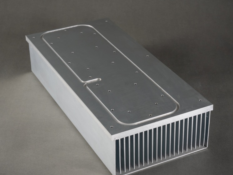
A heat sink is a thermally conductive component that pulls heat away from an electronic device — typically a CPU, MOSFET, IGBT, or LED — and transfers it to a surrounding fluid, usually air. Its job is simple in principle but critical in practice: keep junction temperatures within safe limits so the device runs reliably and lasts its rated lifetime.
At the highest level, heat sinks fall into two families. Passive heat sinks rely on natural convection — no moving parts, silent, and maintenance-free. Active heat sinks add forced airflow (usually a fan) to handle higher heat loads in a smaller footprint.
To make sense of the dozens of options on the market, this guide classifies heat sinks along three axes:
- By airflow method — active (fan-assisted) vs passive (natural convection)
- By material — aluminum, copper, or hybrid (aluminum body with copper insert or base)
- By manufacturing process — extruded, bonded, skived, forged, die-cast, CNC-machined, stamped, or zipper fin
Every heat sink you’ll encounter is a combination of choices along these three axes — and each combination carries its own cost, performance, and lead-time trade-offs.
Heat Source and Heat Transfer Basics
Before choosing a heat sink, it helps to understand what you’re actually trying to cool — and how heat physically moves out of the device.
Common heat sources in electronics include CPUs and GPUs, IGBTs and MOSFETs in power converters, LED arrays in lighting and displays, RF power amplifiers, and battery management modules in EVs and energy storage systems. Each produces heat differently, which directly shapes the cooling strategy.
Three heat transfer mechanisms are at work in every heat sink:
- Conduction — heat flows from the silicon die, through the thermal interface material (TIM), into the heat sink base and up through the fins. This is where material thermal conductivity matters most.
- Convection — heat moves from the fin surfaces into the surrounding air (or liquid). Fin geometry and airflow dominate here.
- Radiation — usually a minor contributor, but black-anodized surfaces can add 5–10% extra dissipation in still-air, passive applications.
Not all heat is the same. Designers need to distinguish between steady-state heat (continuous load), transient or peak heat (short bursts during startup or switching), and hotspot vs distributed heat (a concentrated die vs a spread-out PCB).
This last point matters: a 100 W chip with a 1 cm² hotspot (100 W/cm²) is a completely different cooling problem than a 100 W LED array spread over 50 cm² (2 W/cm²). High heat flux — not total wattage — is what pushes designs toward copper, vapor chambers, or hybrid solutions.
Active Heat Sinks and Forced-Air Solutions
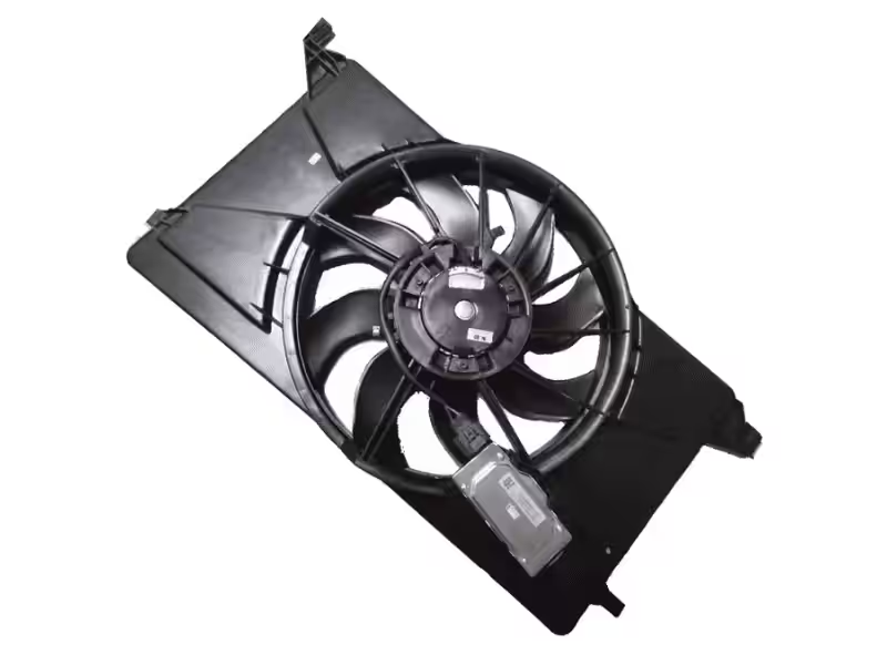
An active heat sink combines a finned heat sink with a fan or blower to force air across the fins. By replacing slow natural convection with high-velocity airflow, the same heat sink can dissipate 3–5× more heat — or shrink to a fraction of the size for the same thermal load.
When forced-air cooling makes sense:
- Heat dissipation exceeds roughly 25–30 W in a compact enclosure
- Available space won’t allow a larger passive design
- Airflow direction can be controlled (sealed chassis, ducted servers, telecom cabinets)
- The application tolerates some acoustic noise and a moving part in the BOM
Trade-offs to weigh:
| Pros | Cons |
|---|---|
| Higher thermal performance per unit volume | Fan noise (often 25–45 dBA) |
| Smaller overall footprint | Moving part = finite MTBF, eventual failure |
| Predictable, tunable airflow | Dust ingress clogs fins over time |
| Lower cost than scaling up passive material | Adds 1–10 W of power draw and a control circuit |
In short: active cooling buys you performance and size — at the cost of reliability, noise, and ongoing maintenance. For consumer electronics and servers, that trade is usually worth it; for sealed outdoor or industrial enclosures, it often isn’t.
Passive Heat Sinks and Natural Convection
A passive heat sink has no fan, no pump, no moving parts — it sheds heat purely through natural convection and a small amount of radiation. Hot air rises off the fins, cooler air flows in to replace it, and the cycle repeats. Simple, silent, and effectively maintenance-free for the life of the product.
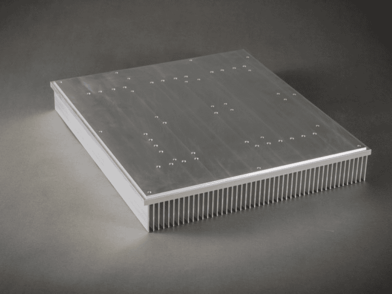
Fin orientation is critical. Vertical fins create a “chimney effect” that pulls air upward through the fin channels, maximizing convective flow. Mount the same heat sink horizontally and efficiency can drop by 30% or more — a frequent and costly oversight in field installations.
Passive designs are the right choice for:
- Fanless industrial controllers, medical devices, and instrumentation where silence and zero maintenance matter
- Outdoor telecom enclosures, roadside cabinets, and base stations exposed to dust, moisture, and temperature swings
- Sealed IP65/IP67-rated equipment where any air intake is a contamination risk
- LED lighting and signage expected to run 50,000+ hours without service
Practical upper limit: roughly 50–75 W with a generously sized extrusion or bonded-fin design. Beyond that, you’ll need heat pipes, a much larger sink, or you’ll have to accept a fan.
Materials: Aluminum Heat Sinks vs Copper Heat Sinks
The choice between aluminum and copper is one of the first — and most consequential — decisions in heat sink design. It directly affects thermal performance, weight, cost, and manufacturability.
Aluminum Heat Sinks
Aluminum is the workhorse of the thermal management industry, and for good reason. It’s lightweight (roughly one-third the density of copper), highly cost-effective, and exceptionally extrudable — meaning complex fin profiles can be produced in long, consistent runs at low unit cost.
Performance-wise, aluminum delivers approximately 60% of copper’s thermal conductivity (~200 W/m·K), but at only about 30% of the raw material cost. For the majority of consumer, industrial, and telecom applications, that trade-off is unbeatable.
The industry-standard alloy is AL6063-T5, prized for its clean extrusion behavior, anodizing compatibility, and balance of strength and thermal performance. AL6061 is also common where higher mechanical strength is needed.
Copper Heat Sinks
When heat density climbs, copper earns its premium. With a thermal conductivity around 400 W/m·K — nearly double that of aluminum — copper excels at pulling heat away from concentrated hotspots before it can spread or saturate the base.
The drawbacks are real, however:
- ~3× heavier than aluminum, which complicates mounting, shipping, and vibration design
- Significantly higher raw material cost, often 4–6× per kilogram
- Harder to machine and extrude; copper is typically skived, bonded, or CNC-milled rather than extruded into complex profiles
- Prone to oxidation, usually requiring nickel plating for long-term appearance and corrosion resistance
Copper is the right call for high-heat-density applications: server-grade CPUs and GPUs, laser diodes, RF power amplifiers, dense IGBT modules, and medical imaging electronics — anywhere heat flux exceeds what aluminum can spread efficiently.
A common hybrid approach: use a copper insert or base plate under the hotspot for rapid heat spreading, paired with aluminum fins for lightweight, cost-effective convection. This delivers copper-level performance where it matters and aluminum-level economics everywhere else — the best of both worlds.
From Our Manufacturing Floor: When the “Aluminum vs Copper” Question Is the Wrong Question
Over years of producing heat sinks for power electronics, EV chargers, and 5G base stations, we’ve observed engineers often treat material choice as binary — when the optimal answer is frequently a hybrid.
A common scenario: a customer specifies full copper because hotspot temperature is too high in simulation. But the heat flux is actually concentrated in a small die footprint. In these cases, an aluminum body with an embedded copper insert (or a copper base friction-stir-welded to an aluminum fin stack) delivers nearly equivalent performance at 40–60% of the weight and substantially lower cost.
Our field-tested guidance:
- Heat flux <30 W/cm² → AL6063 is almost always sufficient
- Heat flux 30–60 W/cm² with localized hotspot → aluminum body + copper insert is the best cost/performance balance
- Heat flux >60 W/cm², or extreme fin density → full copper is justified
One manufacturing fact that drives this decision: copper can be skived as thin as 0.1mm; aluminum’s practical limit is 0.2mm. Sometimes the real reason to choose copper isn’t conductivity — it’s manufacturability of extreme fin geometry.
Manufacturing-Based Heat Sink Types
Heat sinks are classified not only by material and geometry, but also by how they’re manufactured. Each process imposes distinct limits on fin thickness, height, density, and cost — and choosing the right process is often as important as choosing the right material.
Extruded Heat Sinks
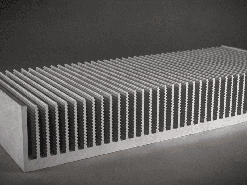
Extrusion is the most cost-effective process for medium-to-high volume production. Heated aluminum billet is forced through a shaped die, producing continuous profiles that are then cut to length.
- Practical fin aspect ratio: up to ~23 (fin height ÷ fin gap)
- Minimum fin thickness: ~0.8 mm
- Maximum cross-section width: ~330 mm on standard presses
- Best for: telecom equipment, industrial motor drives, general-purpose power electronics
- Sample lead time: ~30 days (custom die tooling required)
Bonded Heat Sinks
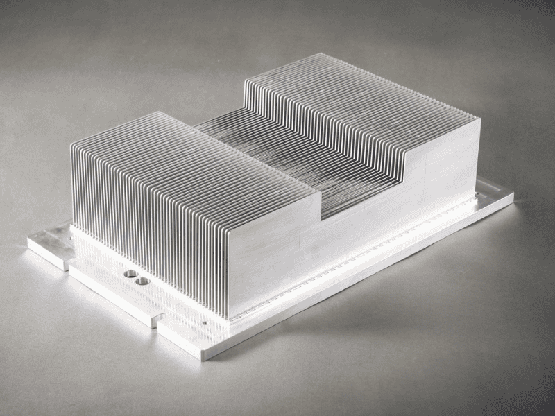
Bonded fin heat sinks feature fins mechanically pressed and epoxy-bonded into a grooved base — a method that breaks free of the extrusion press width limit and allows mixed materials, such as an aluminum base with copper fins.
- Fin thickness: 0.5–3 mm; fin height: up to 150 mm; fin pitch: from 2.5 mm
- Best for: very large surface areas exceeding extrusion’s cross-section limit
- Trade-off: a small contact thermal resistance exists at the fin-to-base interface
- Sample lead time: ~15 days
Skived Fin Heat Sinks
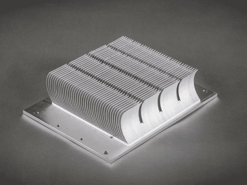
Skiving uses a precision blade to “shave” fins directly from a solid metal block, leaving fins and base as one continuous piece — zero contact resistance at the interface.
- Fin thickness: 0.2–2 mm (aluminum), 0.1–1 mm (copper)
- Fin height: up to 120 mm (aluminum) or 50 mm (copper)
- Best for: high fin density in compact envelopes, GPU/CPU cooling, RF power amplifiers
- Tooling: none required → fastest sample turnaround at ~10 days
Skiving is the go-to process when you need maximum surface area in minimum volume and can’t afford the thermal penalty of a bonded interface.
Cast and Forged Heat Sinks
Die casting enables complex 3D geometries and integrated mounting features (bosses, brackets, shrouds) in a single part — though cast aluminum alloys typically have lower thermal conductivity (~100–150 W/m·K) than wrought 6063.
Cold forging produces dense pin-fin arrays ideal for omnidirectional natural convection — pins shed heat regardless of airflow direction. Tooling cost is high, making this process best suited to very high-volume applications like LED lighting and automotive lamps.
CNC, Stamped, and Zipper Fin Methods
- CNC machining: unmatched flexibility for complex geometries, tight tolerances, prototypes, and low-volume custom parts — no tooling cost, but high per-unit machining time
- Stamped fins: very low cost for low-power consumer electronics and small thermal loads
- Zipper fin (folded fin): ultra-thin folded sheet fins soldered or brazed to a base — excellent surface-area-to-weight ratio, widely used in telecom, server, and networking equipment
Comparison Summary
| Type | Sample Lead Time | Fin Thickness | Tooling Cost | Best Volume |
|---|---|---|---|---|
| Extruded | ~30 days | ≥ 0.8 mm | Medium | High |
| Bonded | ~15 days | 0.5–3 mm | Medium | Medium–High |
| Skived | ~10 days | 0.1–2 mm | None | Any |
| CNC | 5–7 days | Flexible | None | Low |
| Forged | 45+ days | Pin-fin | High | Very High |
Quick selection tip: For prototyping or urgent samples, skiving or CNC gets you to a testable part fastest. For locked-in mass production, extrusion almost always wins on unit cost — provided your fin geometry fits within its physical constraints.
Water-Based and Two-Phase Cooling Types
When heat loads climb beyond what air cooling can practically handle — or when system enclosures restrict airflow — liquid and two-phase cooling become essential. These technologies don’t just incrementally improve performance; they operate on a fundamentally different order of thermal resistance.
Liquid Cold Plates
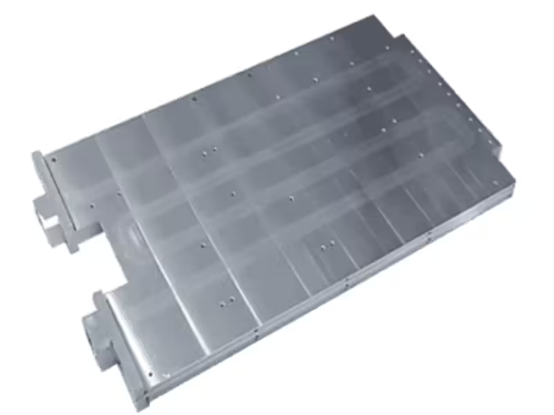
Liquid cold plates are machined or friction-stir-welded aluminum or copper plates with internal flow channels that carry coolant (typically water-glycol) directly past the heat source. They are the backbone of thermal management in:
- EV inverters and onboard chargers
- EV battery pack cooling
- High-power lasers and medical imaging
- Hyperscale data center direct-to-chip cooling
A key manufacturing enabler is friction stir welding (FSW) — a solid-state joining process that produces leak-tight, high-pressure-rated channels and even allows aluminum-to-copper hybrid construction, combining copper’s spreading capability under the die with aluminum’s weight and cost advantages elsewhere.
Heat Pipes and Vapor Chambers
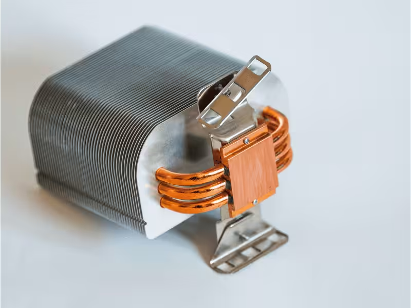
Heat pipes are sealed, passive two-phase devices using an evaporation–condensation cycle inside a wicked tube. Their effective thermal conductivity exceeds 10,000 W/m·K — roughly 25× that of solid copper — yet they require no pump and no power.
Vapor chambers are the planar equivalent of heat pipes, ideal for spreading concentrated hotspots uniformly across a larger base before fins or a cold plate take over. They’re now standard in high-end GPUs, gaming laptops, and 5G mMIMO radios.
When to Step Up to Liquid
As a general rule, liquid cooling becomes the right choice above ~300–500 W of dissipation, or in any system where airflow is restricted, acoustics are critical, or ambient temperatures are uncontrolled.
Thermal Resistance at a Glance
| Cooling Approach | Typical Thermal Resistance (°C/W) |
|---|---|
| Air-cooled, extruded | 0.5 – 2.0 |
| Air-cooled, skived / bonded | 0.1 – 0.5 |
| Liquid cold plate | 0.01 – 0.05 |
The numbers tell the story: moving from a premium air-cooled sink to a liquid cold plate drops thermal resistance by an order of magnitude — often the only path to keeping junction temperatures in spec as power densities continue to climb.
Thermal Interface Materials and Attachment

Even the best-designed heat sink will underperform if the thermal interface between the heat source and the sink is poorly chosen. Microscopic air gaps between two “flat” metal surfaces are the enemy — and the role of a thermal interface material (TIM) is to displace that air with a much more conductive medium.
Common TIM Options
| TIM Type | Typical Conductivity (W/m·K) | Best For |
|---|---|---|
| Thermal grease (paste) | 3 – 12 | CPUs, GPUs, high-performance applications |
| Thermal pads | 1 – 8 | Uneven surfaces, gap-filling, easy assembly |
| Phase-change materials (PCM) | 3 – 8 | Production environments needing pre-applied, mess-free TIM |
| Graphite sheets | 400+ (in-plane) | Thin form factors, mobile/consumer electronics |
| Liquid metal | 70+ | Extreme performance (gaming, overclocking) — handle with care; conductive and corrosive to aluminum |
Why TIM Choice Matters More Than Engineers Expect
A poorly chosen or poorly applied TIM can add 0.2–0.5 °C/W to the thermal path — sometimes more than the heat sink itself contributes. We’ve seen designs where the customer specified a premium skived copper sink, then negated half its benefit with a low-grade thermal pad. The interface is not a place to cut cost.
Attachment Method: Match to Application
| Method | Mounting Pressure | Reworkable? | Best For |
|---|---|---|---|
| Push-pin / clip | Low–Moderate | Yes | Consumer electronics, easy field service |
| Screw + spring | High, consistent | Yes | High-performance power electronics, telecom |
| Thermal adhesive | N/A (bonded) | No | Permanent installs, vibration-prone environments |
Practical Selection Guidance
- Match TIM to attachment pressure: greases and PCMs need adequate clamping force to thin out into a low-resistance bondline; pads tolerate lower pressure but at higher thermal resistance
- Consider reworkability early: thermal adhesive is unbeatable for vibration and zero-pressure mounting, but ends any chance of field rework — a costly trade-off if your product has a long service life
- Respect PCB and component limits: small surface-mount devices and thin PCBs cannot tolerate the mounting pressure of a screw-and-spring assembly without risk of cracking
- Don’t forget surface flatness: a TIM rated at 8 W/m·K still can’t compensate for a heat sink base that’s warped beyond ~50 µm — flatness specifications belong on the drawing
Rule of thumb: budget the TIM and attachment as a system, not as an afterthought. The cheapest path to a 10% thermal improvement is often a better interface — not a bigger heat sink.
Choosing a Heat Sink Type for Electronic Devices
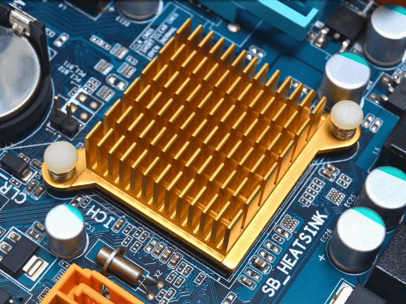
With so many materials, geometries, and manufacturing processes available, selecting the right heat sink can feel overwhelming. The good news: a disciplined selection framework turns the decision into a series of clear, answerable questions — and avoids the costly mistakes we see most often on the manufacturing floor.
Step-by-Step Selection Framework
A reliable selection process follows five sequential steps. Skip any one of them, and you risk over-designing, under-performing, or paying for tooling you didn’t need.
Step 1 — Define the thermal requirements. Gather the fundamentals: component TDP (thermal design power), maximum allowable junction temperature (T_j_max), and worst-case ambient temperature. These three numbers anchor the entire design.
Step 2 — Calculate the target thermal resistance. Use the foundational equation:
Rtotal=Tj,max−TambientPR_{total} = \frac{T_{j,max} – T_{ambient}}{P}Rtotal=PTj,max−Tambient
This is your performance budget — to be divided across junction-to-case, TIM, and sink-to-ambient resistances.
Step 3 — Assess available airflow. Is the system natural convection, or forced air? If forced, what’s the realistic CFM (or LFM) at the sink location, not at the fan outlet? This single input dictates fin pitch, fin height, and whether air cooling is even viable.
Step 4 — Select material and manufacturing process. Balance heat flux, envelope constraints, and production volume against the trade-offs covered in Sections 5–8.
Step 5 — Validate before tooling. Run CFD simulation, then build and test a physical prototype. Never commit to a die until the design is validated — die changes are expensive and slow.
Common Selection Mistakes We See from the Manufacturer’s Side
After reviewing thousands of RFQs and customer drawings, we’ve found the most expensive mistakes rarely come from picking the wrong heat sink type — they come from overlooking manufacturability early in design. Three patterns appear again and again:
Mistake 1 — Designing fin geometry the chosen process cannot produce. A frequent example: an extruded heat sink designed with a fin aspect ratio of 28–30. The practical limit for aluminum extrusion is around 23. Pushing beyond this dramatically increases die cost, scrap rate, and lead time — or becomes physically impossible. If you genuinely need aspect ratios above 23, the conversation should shift early to skived or bonded fins, where the geometry is achievable by design.
Mistake 2 — Choosing the wrong process for project stage and volume. Many customers default to extrusion because of its low per-piece cost, forgetting it requires custom dies and ~30 days for samples. For prototyping or low-volume production, skived fins require no tooling and deliver samples in ~10 days; bonded fins in ~15 days. We routinely advise customers to prototype with skiving and migrate to extrusion only once volumes justify the die investment. This staged approach often saves both weeks of schedule and thousands in scrapped tooling.
Mistake 3 — Specifying performance without specifying airflow. A heat sink rated “0.1 °C/W” only achieves that figure at a specific air velocity — typically 2–3 m/s. We’ve seen customers oversize heat sinks by 40% to compensate for unknown airflow, when adding a small fan or relocating an existing one would have solved the problem at a fraction of the cost. Always characterize actual airflow at the sink location before locking in fin density. A well-fed dense-fin sink will outperform an oversized sparse-fin sink every time.
The takeaway: the best heat sink design is the one that’s manufacturable, validated, and matched to real operating conditions — not the one with the most impressive spec sheet. Loop in your thermal manufacturer during the design phase, not after the drawings are released, and you’ll avoid 90% of the rework we see in this industry.
Design Considerations and Integration
A heat sink doesn’t exist in isolation — it lives inside a real product, with real mechanical, spatial, and reliability constraints. The best thermal performance on paper means nothing if the part can’t be mounted, can’t survive vibration, or won’t fit in the enclosure. These secondary considerations often become primary drivers in the final design.
Fin Efficiency and Geometry
Not all fin surface area contributes equally to heat dissipation. As heat travels from the base out to the fin tip, the local fin temperature drops — meaning the tip dissipates less heat per unit area than the root. This is quantified as fin efficiency, and it has direct design implications:
- Taller, thinner fins suffer diminishing returns. Beyond a certain height, additional fin material adds weight and cost without proportional thermal benefit
- Fin spacing has a sweet spot. The optimal gap is typically 2–3× the thermal boundary layer thickness — too narrow and the boundary layers merge, choking airflow; too wide and surface area is wasted
- Material conductivity sets the optimal height. Copper fins can be taller than aluminum fins before efficiency drops off, because heat travels farther before the temperature gradient flattens
Rule of thumb: if your fin efficiency drops below ~60%, you’re better off adding fins than making existing ones taller.
Mechanical, Space, and Reliability Constraints
Thermal performance is only one axis of the design. The mechanical envelope and reliability requirements often determine what’s actually buildable:

- Mechanical attachment — check early. Confirm PCB warpage limits, mounting hole patterns, and clamping force tolerances before finalizing the sink design. A high-mass copper sink on a thin PCB can crack solder joints under vibration or thermal cycling
- Weight limits matter more than ever. Critical for automotive, aerospace, and portable devices — every gram of copper drives BOM cost, shipping weight, and shock/vibration loading on the PCB
- Enclosure and airflow interactions. Walls, cables, and adjacent components disrupt airflow paths; a sink that performs beautifully in open bench testing may underperform 30% inside the actual chassis
- EMI shielding compatibility. Heat sinks often double as shields or sit adjacent to RF-sensitive areas — verify there are no unintended antenna effects or shielding gaps
- Serviceability and reworkability. Field-replaceable units demand clip- or screw-based attachment, not adhesives — design for the entire product lifecycle, not just first assembly
The smartest thermal designs are the ones developed in parallel with mechanical and electrical engineering — not after the enclosure is finalized. Bring all three disciplines together early, and the integration headaches disappear.
FAQ and Common Pitfalls
Over the years, the same questions come up again and again — from first-time designers and seasoned engineers alike. Here are the ones we hear most often, with straight answers from the manufacturing floor.
Q: Is thermal paste always required? A: For most metal-to-metal interfaces, yes. Even a surface that looks and feels perfectly flat has microscopic peaks and valleys, and the trapped air in those gaps is a thermal insulator (~0.025 W/m·K — roughly 8,000× worse than aluminum). The only common exception is when pre-applied phase-change pads are already factory-installed on the heat sink — don’t double up.
Q: Does a bigger heat sink always perform better? A: No. Beyond a certain size, fin efficiency drops and additional mass yields little to no thermal benefit — only added cost, weight, and assembly difficulty. Adding airflow or switching to a higher-conductivity material almost always beats brute-force upsizing.
Q: Is black anodizing worth it? A: It depends on the cooling mode. For natural convection applications, yes — radiative heat transfer can contribute 10–25% of total dissipation, and a black anodized surface (emissivity ~0.85) significantly outperforms bare aluminum (~0.05). For forced convection, convection dominates so heavily that the radiation gain is marginal — anodizing then becomes a corrosion-protection and aesthetics decision, not a thermal one.
Q: Can I use a heat sink without any fan if the TDP is under 10 W? A: Often yes, but it depends on enclosure ventilation and orientation. Vertical fins in an open chassis can passively dissipate 10–15 W; the same sink horizontally mounted in a sealed box may struggle with 5 W. Always validate in the real enclosure.
Q: Copper or aluminum — which should I default to? A: Aluminum, unless heat flux exceeds ~50 W/cm² or weight is not a constraint. Copper’s thermal advantage is real but rarely justifies its 3× weight and 4–5× cost penalty for typical electronics.
Summary and Next Steps
The selection workflow is straightforward: thermal requirements → airflow → material → manufacturing process → validation. Two principles matter most: decide material and manufacturability together, and engage your manufacturing partner during simulation, before drawings are frozen.
Before release, confirm thermal simulation at worst-case ambient, verified airflow, supplier-reviewed manufacturability, validated TIM and attachment, and prototype testing under representative load. Share your thermal specifications with us — TDP, ambient, envelope, target thermal resistance, and volume — for a free manufacturability and material recommendation.