
Choosing the wrong heat sink can quietly inflate your BOM cost by 30% — or cause field failures six months after launch.
For 15+ years, we’ve produced tens of millions of heat sinks annually for power electronics, 5G, EV charging, and high-power computing. This guide shares what we’ve learned on the production floor — not in textbooks.
You’ll get the 8 design decisions that actually move the needle: material selection, manufacturing process, fin geometry, surface treatment, and the cost tradeoffs behind each.
New to thermal management? Start with what a heat sink is and main types of heat sinks. Then come back here to go deeper.
Compare Heat Sink Materials
The single biggest decision in heat sink design is not fin shape or fan curve. It is material selection. Get this wrong, and no amount of geometry optimization will save your thermal budget or your BOM cost.
Here is how the four most common materials compare:
Heat Sink Material Comparison Table
| Material | Thermal Conductivity (W/m·K) | Density (g/cm³) | Relative Cost | Best For |
|---|---|---|---|---|
| Aluminum 6063 | 201 | 2.70 | 1.0x (baseline) | Extruded profiles, general-purpose |
| Aluminum 1050 | 229 | 2.71 | 1.1x | Stamped or bent fins, higher conductivity |
| Copper C1100 | 398 | 8.96 | 3.5–4x | Localized hotspots, CPU/GPU cold plates |
| Graphite | 100–1500 (anisotropic) | 1.8–2.2 | 5–8x | Ultra-thin, weight-critical applications |
Key Takeaways from the Numbers
Copper conducts about 2x better than aluminum, but it is also 3.3x heavier and 3.5 to 4x more expensive. For a 500g aluminum heat sink, switching to pure copper means roughly 1.65 kg of metal and about 4x the material cost.
Aluminum 6063 vs. 1050: Alloy 1050 offers around 14 percent better conductivity at only a 10 percent cost premium, but it is softer and harder to extrude into complex fin profiles. 6063 wins on manufacturability; 1050 wins on raw thermal performance for simple geometries.
Graphite is a specialist material. It is anisotropic, meaning it conducts much better in-plane than through-plane, and it is brittle. Reserve it for tablets, thin laptops, or aerospace applications where every gram matters.
From the Production Floor
Roughly 85 percent of the heat sinks we manufacture use aluminum, not because copper is thermally inferior, but because at scale, the weight and cost penalties make pure copper impractical for most applications.
The sweet spot is hybrid design:
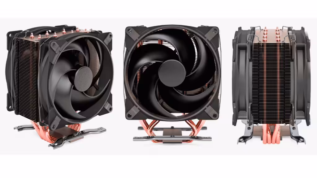
- Aluminum fins bonded to a copper base to spread heat from concentrated hotspots
- Aluminum body with embedded copper heat pipes to move heat to remote fin areas
These hybrid structures capture 70 to 85 percent of full-copper thermal performance at 40 to 50 percent of the weight and cost. For nine out of ten production designs, this is the right tradeoff.
Quick Decision Guide
- Cost-sensitive, high-volume consumer product: Aluminum 6063
- Localized hotspot above 100 W/cm²: Copper base with aluminum fins
- Tight space, remote heat source: Aluminum body with embedded heat pipes
- Below 2 mm thickness, weight-critical: Consider graphite
Next, we will examine how manufacturing process interacts with material choice, because the best material on paper is not always the cheapest one to actually build.
The Case for Copper
Copper is the highest-performing metal commonly used in heat sinks, but higher performance does not always mean better value. The real question is not “is copper better than aluminum?” It is “is copper better enough to justify 3.3x the weight and 3.5x the cost?”
In most cases, the answer is no. In specific cases, the answer is absolutely yes.
When Copper Genuinely Outperforms Aluminum
Copper earns its premium in three scenarios:
- High heat flux density (above 50 W/cm²): When a small die or hot zone dumps a large amount of heat into a small footprint, aluminum cannot spread it fast enough. Copper’s higher conductivity prevents localized hotspots.
- Thin-profile constraints: When vertical space is limited and you cannot grow fin height, copper moves more heat through less cross-section.
- Transient thermal loads: Copper’s higher volumetric heat capacity buffers short power spikes better than aluminum.
The Cost and Weight Penalty, Quantified
For a typical 500g aluminum heat sink, switching to full copper means:
| Metric | Aluminum 6063 | Copper C1100 | Penalty |
|---|---|---|---|
| Weight | 500 g | 1,650 g | +230 percent |
| Material cost | 1.0x | 3.5 to 4x | +250 to 300 percent |
| Thermal performance gain | baseline | +25 to 40 percent | modest |
The performance gain is real, but it is rarely proportional to the weight and cost penalty unless your design is already thermally limited.
From the Production Floor
We reserve copper, typically in copper-pipe or copper-insert hybrid designs, for heat flux densities above roughly 50 W/cm², where aluminum simply cannot spread heat fast enough. Below this threshold, the 3.3x weight penalty and 3.5x cost rarely justify themselves.
A real tradeoff we have seen on the floor: a customer initially specified full copper for a 30 W/cm² application. After prototype testing, an aluminum base with embedded copper heat pipes delivered within 8 percent of full-copper thermal performance at 40 percent of the weight, and roughly half the unit cost.
The lesson: before committing to full copper, prototype a hybrid. In nine out of ten cases, the hybrid wins on total value.
Quick Decision Rule
- Heat flux above 50 W/cm² and weight is not critical: Full copper or copper base with aluminum fins
- Heat flux 20 to 50 W/cm² with hotspot concerns: Aluminum body with embedded copper heat pipes
- Heat flux below 20 W/cm²: Stay with aluminum, copper rarely pays off
Next, we will look at how manufacturing process (extrusion, skiving, forging, bonded fin) shapes both cost and the maximum fin density you can achieve.
Extruded Aluminum Heat Sinks: Process and Limits
Extrusion is the workhorse of the heat sink industry. If you have ever held a finned aluminum profile from a desktop PC, an LED driver, or an industrial inverter, chances are it came off an extrusion press. The reason is simple: no other process matches extrusion on cost per kilogram at volume.
But extrusion also has hard physical limits. Understanding both the economics and the constraints upfront will save weeks of tooling rework later.
Why Extrusion Dominates Volume Production
Extruded aluminum remains our highest-volume process, with annual profile output measured in thousands of tons. The economics are unmatched below a 16 to 1 fin aspect ratio. Once a die is paid for, per-meter cost drops dramatically, and aluminum 6063 extrudes cleanly with excellent surface finish straight off the press.

The Extrusion Workflow, Step by Step
- Billet preheat to 450 to 500 degrees Celsius
- Press through die under 1,500 to 4,000 tons of force
- Quench and stretch-straightening to lock in temper and remove bow
- Age hardening to T5 or T6 temper for mechanical strength
- Cut to length and secondary CNC for mounting holes, slots, and tapped features
Each step has its own tolerance stack, but the die itself is where 80 percent of the final quality is determined.
Hard Limits You Will Hit in Production
| Constraint | Typical Limit | Why It Matters |
|---|---|---|
| Maximum fin aspect ratio | 12 to 1, up to 16 to 1 | Beyond this, fins tear or wave during press |
| Minimum fin thickness | About 1.0 mm | Thinner fins cool too fast and crack |
| Maximum profile width | 300 to 400 mm | Limited by press tonnage and die strength |
| Minimum fin gap | About 2.0 mm | Tighter gaps starve metal flow |
If your design exceeds these limits, you are no longer in extrusion territory. Skiving, bonded fin, or forging becomes the next conversation.
From the Production Floor
New extrusion dies take 3 to 5 weeks to design, machine, and trial on the press. Die rework after first samples is the number one schedule killer we see in this industry.
The fix is not faster tooling, it is better upfront engineering. Invest in CFD simulation and DFM review before cutting steel. A two-day DFM review has saved customers four weeks of die rework on more than one occasion.
A practical rule: if your fin aspect ratio is above 14 to 1 or your fin thickness is below 1.2 mm, expect at least one die trial revision. Budget the schedule accordingly.
Quick Decision Rule
- Aspect ratio below 12 to 1, profile width below 300 mm: Extrusion wins on cost
- Aspect ratio 12 to 1 to 16 to 1: Extrusion possible, but expect tooling iterations
- Aspect ratio above 16 to 1: Move to skiving or bonded fin
Next, we will look at skiving and bonded fin processes, which break through the aspect ratio ceiling that extrusion cannot cross.
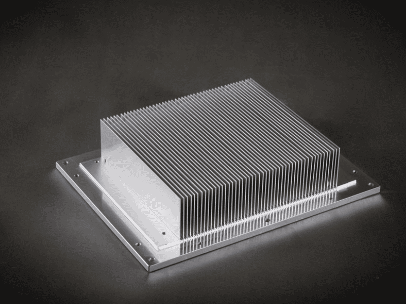
Bonded-Fin Heat Sinks: High-Density Solutions
When extrusion runs out of headroom, bonded-fin construction takes over. By assembling fins and base as separate pieces and then joining them, you escape the metal-flow physics that cap extruded designs. The result: fin densities that would tear a die apart on an extrusion press.
This is the process behind most high-end telecom, server, and power electronics heat sinks you will find in the field.
Why Bonded Construction Breaks Extrusion Limits
Extrusion forces molten aluminum to flow simultaneously into every fin channel. Above a 16 to 1 aspect ratio, flow becomes unstable and fins tear or wave. Bonded construction sidesteps this entirely. Fins are pre-cut from sheet or extruded stock, then assembled into a machined base.
The payoff is dramatic: bonded-fin construction lets us push fin aspect ratios to 30 to 1 or beyond, roughly 2 to 3x what extrusion allows. We typically deploy this for telecom base stations and high-density server applications where airflow is tight and surface area must be maximized.
Three Bonding Methods Compared
| Method | Thermal Interface | Cost Premium | Best Use Case |
|---|---|---|---|
| Epoxy bonding | About 0.3 degrees Celsius cm² per watt | Lowest, baseline | Cost-sensitive, moderate heat flux |
| Brazing | Near zero | Plus 25 percent | High-performance, high-reliability |
| Mechanical press-fit plus epoxy | About 0.15 degrees Celsius cm² per watt | Plus 10 to 15 percent | Balanced cost and performance |
Brazing delivers the best thermal path but requires controlled-atmosphere furnaces and tighter fixturing. Epoxy is simpler but adds a measurable thermal resistance layer. Press-fit plus epoxy is the middle road we recommend for most industrial applications.
Quality Control: Where Bonded Designs Fail
The bond line is everything. Bonding voids exceeding 5 percent of contact area can spike thermal resistance by 15 to 20 percent. This is not a small effect, it is enough to push a marginal design into thermal shutdown.
We 100 percent inspect bond lines on production lots. Under our ISO 9001 certified process, it is not optional. Voids, misalignment, and epoxy squeeze-out are all caught before shipment.
Extruded vs Bonded-Fin Decision Table
| Factor | Extruded | Bonded-Fin |
|---|---|---|
| Fin aspect ratio | Up to 16 to 1 | 30 to 1 or higher |
| Unit cost (relative) | 1.0x | 1.8 to 2.5x |
| Tooling cost | 3,000 to 8,000 USD per die | Minimal |
| Lead time (first article) | 4 to 6 weeks | 2 to 3 weeks |
| Best volume range | 5,000 plus units per year | 500 to 50,000 units per year |
The crossover point is usually clear. Below 16 to 1 aspect ratio and above 5,000 units per year, extrusion wins. Above 16 to 1 or below 5,000 units per year, bonded-fin wins on either performance or total cost.
Quick Decision Rule
- Fin aspect ratio above 16 to 1: Bonded-fin is your only option
- Low to medium volume, tight schedule: Bonded-fin avoids die tooling lead time
- Mission-critical thermal performance: Brazed bonded-fin, no compromise
Next, we will look at skived fin heat sinks, a single-piece alternative that delivers bonded-fin density without a bond line at all.
Fin Geometry and Density Optimization
Fin geometry is where heat sink design stops being a metallurgy problem and becomes a fluid dynamics problem. The right fin shape and density depends almost entirely on one variable: how much air is actually moving across the fins.
Get this match right, and a modest aluminum heat sink outperforms a heavier, more expensive one. Get it wrong, and you have built an aerodynamic wall instead of a thermal solution.
The Fin Density vs Airflow Tradeoff
More fins means more surface area, which sounds like more cooling. But more fins also means narrower gaps, higher pressure drop, and slower air. At some point, the air simply stops flowing through the densest part of the fin stack, and the extra surface area becomes dead weight.
The honest rule: fin density must be matched to available airflow, not maximized in isolation.
Four Common Geometries and Where Each Wins
| Geometry | Process | Best Airflow Range | Best Use Case |
|---|---|---|---|
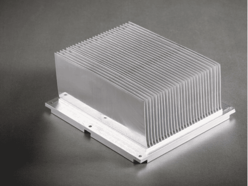
| Straight fin | Extruded | Above 200 LFM | Directed forced airflow, ducted systems |
| Pin fin | Forged or bonded | Below 100 LFM | Omnidirectional or natural convection |
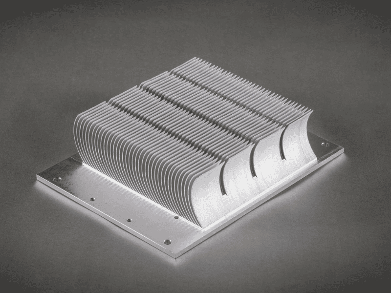
| Flared fin | Extruded with secondary | Natural convection or high CFM | Chimney-effect designs, telecom enclosures |
| Skived fin | Skiving | Above 400 LFM | Ultra-high density on solid base, gap below 1 mm |
Straight fins are the default for forced-air systems where airflow direction is known and controlled. Pin fins shine where airflow direction is uncertain, since they cool equally well from any angle. Flared fins help natural-convection designs where rising hot air needs an exit path.
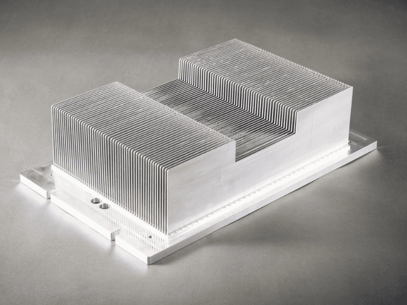
Skived Fin: A Special Case Worth Knowing
Skived fins are cut from the solid base material itself, so there is no bond line and no joint resistance. This makes skived fins ideal when you need extreme density (sub-1 mm gaps) on a solid copper or aluminum base, typically for high-power CPUs, GPUs, and laser diodes.
The catch: skived fins are limited to relatively small footprints, and the process is slower than extrusion.
From the Production Floor
Doubling fin count from 20 to 40 in a 100 mm profile typically improves thermal resistance by only 12 to 18 percent, while increasing pressure drop by 40 to 60 percent. Past a certain point, you are choking airflow, not improving cooling.

The rule we apply on every project: match fin pitch to available LFM.
- Below 100 LFM: Pin fins or sparse straight fins (pitch above 5 mm) win
- 100 to 400 LFM: Standard straight fins (pitch 2 to 4 mm) hit the sweet spot
- Above 400 LFM: Dense bonded or skived fins (pitch below 2 mm) deliver
We have seen customers specify 1.5 mm fin pitch for a natural-convection enclosure. The result was a heat sink that performed worse than a 4 mm pitch design at half the weight. The dense fins simply blocked airflow.
Heat Pipes and Vapor Chambers Integration
When a heat sink base is no longer big enough to spread heat efficiently, passive two-phase devices take over. Heat pipes and vapor chambers move heat by evaporating and condensing a working fluid inside a sealed copper envelope, transferring heat tens of times more effectively than solid metal of the same cross-section.
The question is not whether they work, it is when adding them is worth the cost and assembly complexity.
When to Add Heat Pipes
Solid metal bases work fine when the heat source sits directly under the fin field. The trouble starts when heat must travel laterally before it reaches the fins. Aluminum’s thermal conductivity, while respectable, is not infinite, and spreading resistance can dominate the total thermal budget.
We integrate copper heat pipes when hotspot-to-fin distance exceeds approximately 50 mm, or when spreading resistance becomes the dominant thermal bottleneck in our simulation. A well-integrated heat pipe can reduce effective spreading resistance by 40 to 60 percent compared to a solid aluminum base of the same footprint.
Typical applications: server CPU coolers with offset fin stacks, telecom modules where the heat-generating IC sits at one end of a long enclosure, and LED arrays with non-uniform power distribution.
Vapor Chambers for Extreme Hotspots
Vapor chambers are essentially flat, planar heat pipes. They spread heat in two dimensions instead of one, which makes them the right choice when the hotspot is small and the fin field is large.
We specify vapor chambers when the hotspot spread budget drops below 5 mm, typical in high-power-density processors, GPUs, and laser diodes. Below this threshold, even multiple parallel heat pipes cannot spread heat fast enough to prevent local temperature spikes.
Mechanical Integration QC Checks
Two-phase devices add performance, but they also add failure modes. Production checks we never skip:
| Check | Limit | Why It Matters |
|---|---|---|
| Heat pipe flattening | 30 to 40 percent of original diameter maximum | Beyond this, the internal wick structure can crack, killing capillary action |
| Solder joint pull strength | Greater than 50 N for embedded heat pipes | Weak joints create air gaps and thermal interface failure |
| Helium leak test | 100 percent of vapor chambers before shipping | A single pinhole leak turns a vapor chamber into a dead copper plate |
A heat pipe that has been over-flattened or poorly soldered can look perfect on the outside while delivering near-zero thermal benefit. This is why incoming inspection and in-process checks are non-negotiable.
When heat pipes and vapor chambers are integrated correctly, they unlock thermal performance that no amount of fin optimization can match. Next, we will look at how surface treatment and finishing affect both thermal performance and long-term reliability.
Performance Metrics, Testing, and Validation
A heat sink design is only as good as the data that proves it works. Datasheet numbers and CFD simulations are starting points, not conclusions. Without disciplined physical testing, you are shipping assumptions instead of thermal solutions.
Here is the qualification framework we apply to every production heat sink before it leaves the factory.
The Four Metrics We Report on Every Qualification
| Metric | What It Measures | Why It Matters |
|---|---|---|
| Rθ (case-to-ambient) | °C/W at specified airflow | The headline number for thermal capability |
| Delta-T at heat source | Measured with calibrated thermocouples | Validates real junction temperature, not just sink temperature |
| Pressure drop curve | Across full LFM/CFM operating range | Tells the system designer how hard the fan must work |
| Acoustic signature | dBA at 1 m, for fan-integrated assemblies | Increasingly critical for telecom, medical, and consumer applications |
A qualification report missing any of these four leaves the customer guessing. Rθ alone, the most commonly quoted metric, is meaningless without knowing the airflow it was measured at and the pressure drop it imposed.
Test Environment Requirements
Repeatable thermal data demands a controlled environment. Our standard: wind tunnel with calibrated ducting and ±0.5°C thermal stability. Anything less and your numbers do not repeat from one test session to the next, which makes design comparisons unreliable.
Open-bench testing with a desk fan blowing across the sample is not validation, it is theatre.
TIM Selection and Contact Resistance
The thermal interface material between heat source and heat sink is often the weakest link in the chain. A great heat sink defeated by a poor TIM choice is a common, expensive mistake.
Typical contact resistance ranges we measure:
| TIM Type | Contact Resistance (°C·cm²/W) | Best Use Case |
|---|---|---|
| Thermal grease | 0.05 to 0.15 | High-performance, low-volume assembly |
| Phase change pads | 0.10 to 0.25 | Mass production, rework-friendly |
| Graphite pads | 0.20 to 0.40 | Reusable, dry-handling environments |
Grease delivers the lowest resistance but adds assembly mess and pump-out risk over thermal cycling. Phase change pads strike a practical balance for most production scenarios.
Prototyping Rule: Same Process as Production
The single rule we enforce above all others: prototype using the same process you will use in production. A CNC-machined “extrusion prototype” lies about manufacturability. We have seen designs pass prototype validation and then fail extrusion die trials because the geometry that machined cleanly could not be extruded at all.
If the production part will be extruded, the prototype must come off an extrusion die. If it will be skived, the prototype must be skived. Anything else is wishful thinking dressed up as engineering.
With validation in place, the final step is choosing the right manufacturing partner. Next, we will cover how to evaluate a heat sink supplier beyond price and lead time.
Choosing the Right Heat Sink and Production Considerations
After seven sections of design theory and material trade-offs, the practical question remains: how do you actually choose? Selection is not about picking the “best” heat sink, it is about matching the right manufacturing route to your heat flux, volume, and tolerance requirements.
Here is the decision framework and production reality we share with every customer at project intake.
Decision Matrix by Heat Flux Density
| If Your Application Has… | Start With… |
|---|---|
| Less than 10 W/cm², high volume, cost-sensitive | Extruded aluminum |
| 10 to 50 W/cm², medium volume, dense fins | Bonded-fin aluminum |
| Greater than 50 W/cm², thermally critical | Aluminum base with copper heat pipes |
| Extreme hotspot, less than 5 mm spread budget | Vapor chamber base |
This matrix is a starting point, not a verdict. Real selection also factors in airflow availability, enclosure constraints, acoustic limits, and total cost of ownership. But if you cannot place your application somewhere on this table, you do not yet have enough data to specify a heat sink.
Production Tolerance Capabilities
Tolerance expectations must match the manufacturing process. Asking an extrusion die to hold CNC tolerances is a recipe for high reject rates and inflated costs.
| Feature | Extrusion | CNC Secondary |
|---|---|---|
| Profile dimension | ±0.15 mm | ±0.05 mm |
| Flatness (base) | 0.1 mm per 100 mm | 0.02 mm per 100 mm |
| Fin pitch | ±0.2 mm | ±0.05 mm |
The practical workflow: extrude to as-cast tolerance, then CNC-machine only the critical interfaces, typically the base flatness and mounting hole pattern. This delivers tight tolerances where they matter without paying for machining where they do not.
Surface Finish Selection by Application
Surface treatment is not cosmetic, it changes thermal and electrical behavior.
- Black anodize: emissivity around 0.85, delivers a 5 to 10 percent gain in natural convection performance. The right choice for fanless designs where radiation matters.
- Clear anodize: corrosion protection with emissivity around 0.15. Use when forced convection dominates and visual consistency matters.
- Chromate conversion: solderable interfaces, low electrical resistance. Specified for RF grounding paths and direct-solder assemblies.
Quality System Credentials
A heat sink that performs in the lab but varies in production is a liability. We operate under ISO 9001 and ISO 14001 certified processes, with 100 percent dimensional inspection on first articles and AQL sampling on production lots.
Ask any potential supplier for their first-article inspection report and their AQL plan. If they cannot produce both on request, you are buying parts, not a thermal solution.
Closing Thoughts
A well-engineered heat sink is the product of disciplined choices across material, geometry, manufacturing process, and validation. The shortcuts are tempting, the consequences are expensive. Whether you are designing a low-cost LED driver or a 500 W server CPU cooler, the same principles apply: define the heat flux, match the process, validate with real data, and partner with a manufacturer who treats tolerance and traceability as non-negotiable.
If you are evaluating a new thermal solution or want a second opinion on an existing design, we are ready to talk specifics.
Ready to Spec Your Next Thermal Solution?
A productive quote starts with a complete spec sheet. Before reaching out, prepare the following inputs so our engineering team can give you accurate, actionable feedback instead of guesswork.
Project Intake Checklist:
- Heat source TDP and footprint
- Maximum allowable junction or case temperature
- Ambient operating range
- Airflow availability (LFM, CFM, or natural convection)
- Mechanical envelope (X, Y, Z constraints)
- Target annual volume
- Required certifications (RoHS, REACH, UL, and others as applicable)
With these seven inputs in hand, our engineering team will return a manufacturability assessment and thermal estimate within 3 to 5 business days, including material recommendation, suggested manufacturing process, and a preliminary Rθ projection.
Missing some of the data? Reach out anyway. We will help you scope what is needed before formal quoting begins.
Continue exploring:

