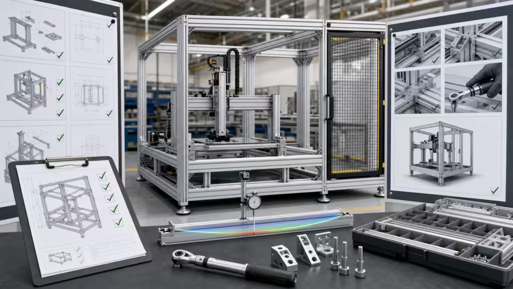
T-slot aluminum profiles are modular extrusions used to build machine frames, guards, workstations, carts, test rigs, robot cells, and other structures without welding every joint. Their longitudinal slots accept nuts, brackets, panels, hinges, cable clips, and a suspicious number of accessories that can make an engineer feel briefly omnipotent.
The system looks simple because assembly is simple. Engineering it well is not. A frame can be strong enough yet too flexible for a camera, linear rail, or measurement fixture. A beam can pass a stress check while its bolted corner slips. Two profiles can both be called “40 series” and still reject each other’s T-nuts with the cold professionalism of incompatible standards.
This guide shows how to choose, calculate, connect, specify, inspect, and validate T-slot aluminum profiles. It also explains where standard framing stops making sense and a custom extrusion or welded structure becomes the better answer.
Quick answer: how do you choose a T-slot aluminum profile?
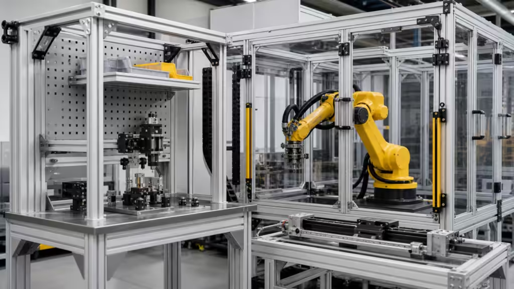
Choose a T-slot aluminum profile by defining the load cases and acceptable movement first. Then select a supplier-specific profile whose section properties, slot geometry, connectors, finish, and machining options meet those requirements. Check the beam, column, joints, complete frame, environment, assembly process, and future changes separately.
Use this order:
- Define static, dynamic, accidental, and service loads.
- Set limits for stress, deflection, vibration, alignment, and racking.
- Obtain the exact supplier datasheet and CAD model.
- Calculate beams and columns in the real orientation.
- Select joints, braces, anchors, and panels as structural components.
- Verify accessories against the actual slot geometry.
- Prototype the highest-risk bay or joint.
- Inspect cut parts and validate the assembled frame before release.
| Design question | Data you need | Common mistake |
|---|---|---|
| Will the beam bend too much? | Span, load position, support condition, E, Ix, Iy | Choosing by outside size only |
| Will the upright buckle? | Effective length, end restraint, axial load, section properties | Treating a column like a short compression block |
| Will the corner move? | Connector type, bolt, torque, friction, load direction | Assuming profile strength equals joint strength |
| Will the frame rack? | Bay geometry, braces, panels, anchors, joint stiffness | Building a rectangle and hoping it behaves like a triangle |
| Will accessories fit? | Slot width, depth, lip shape, thread, series | Mixing parts by nominal series name |
| Will production repeat the prototype? | Cut tolerance, squareness, machining datum, FAI, revision | Approving one hand-fitted sample as a process |
The smallest profile that survives the load is not automatically the best profile. The right one also keeps the machine aligned, remains serviceable, fits the available hardware, and avoids turning assembly into a weekly search for one mythical T-nut.
What is a T-slot aluminum profile?
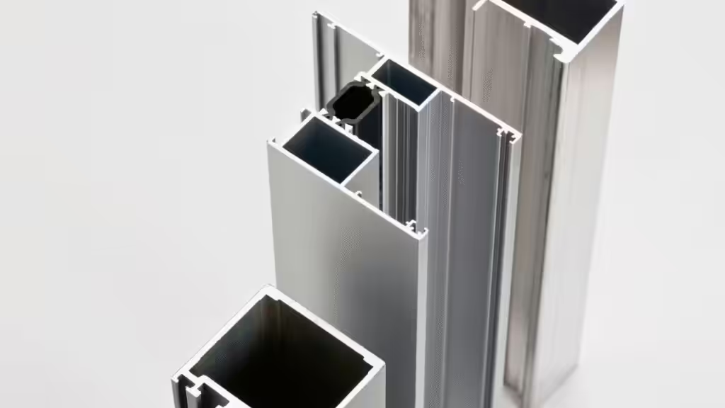
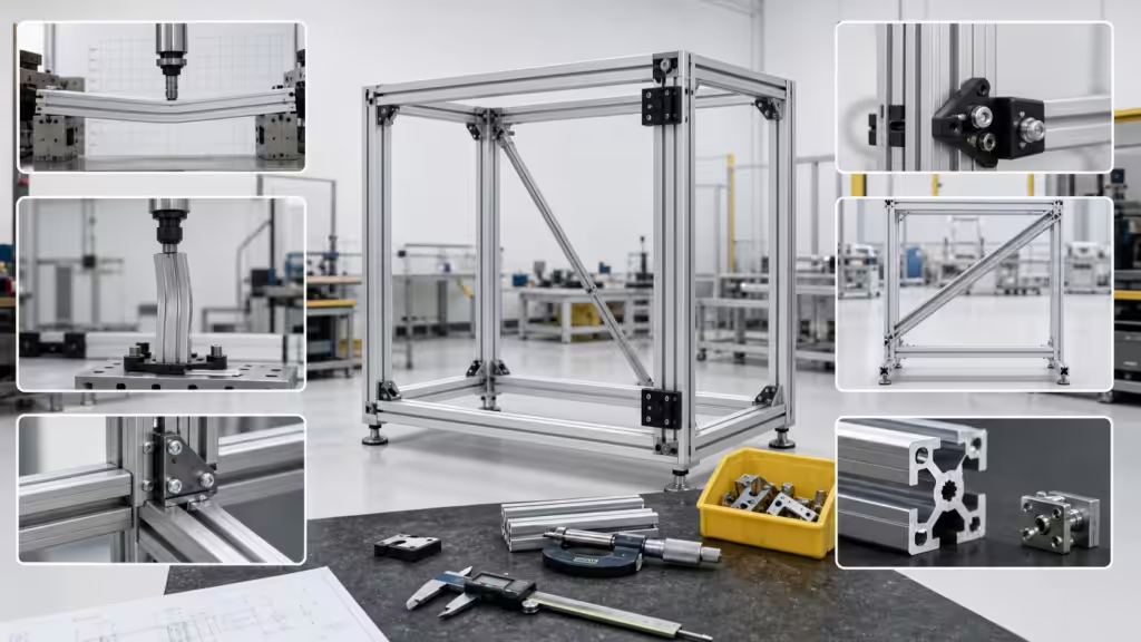
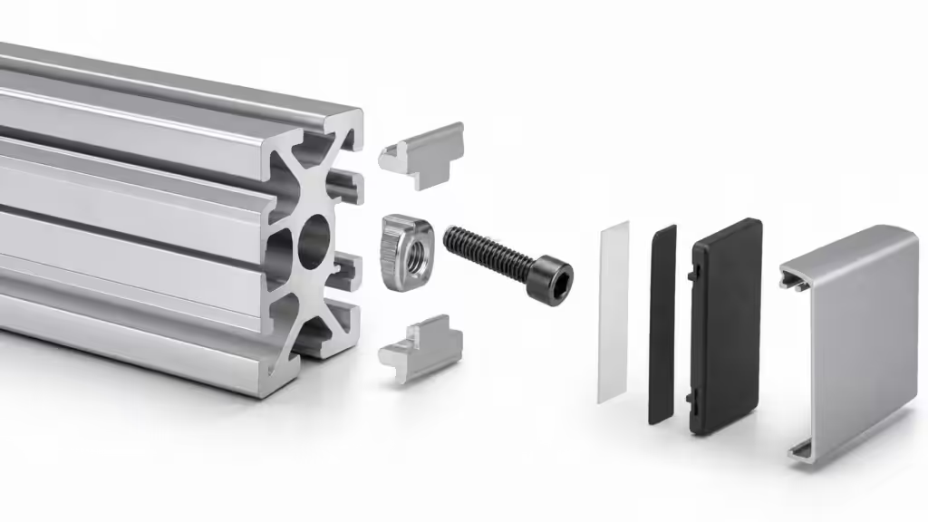
A T-slot aluminum profile is an extruded section with one or more longitudinal channels shaped to retain compatible nuts or connector heads. The nut slides or rolls into the slot. Tightening a bolt clamps a bracket, panel, accessory, or second profile against the extrusion.
The slot is the interface, not just a decorative groove. Its opening, internal width, lip thickness, depth, corner radii, and manufacturing tolerance determine which nuts and connectors engage correctly. The center bore may accept an end tap or special fastener. External grooves can also serve as alignment references, panel tracks, cable routes, or drilling guides.
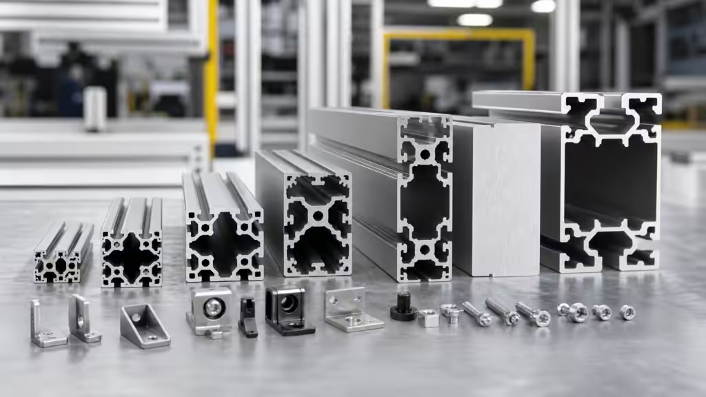
Common profile families include square sections, rectangular sections, smooth-face versions, light and heavy wall versions, and profiles with slots on selected faces. Nominal sizes such as 20 x 20, 30 x 30, 40 x 40, and 40 x 80 mm describe the envelope. They do not fully describe the internal geometry or structural performance.
Why 6063-T6 is common
Many framing systems use 6063-T6 because the alloy extrudes into detailed cross-sections, accepts anodizing well, and provides a practical strength-to-weight balance. The Aluminum Association describes 6xxx-series extrusion products as a first choice for architectural and structural applications because the series is heat treatable, formable, weldable, corrosion resistant, and moderately strong. The exact allowable properties still belong to the selected product and supplier, not to the alloy nickname alone. See the Aluminum Association’s standards overview.
Our internal manufacturing catalog also specifies Aluminum Alloy 6063 for standard and custom extruded thermal products and offers custom anodize colors. That is relevant process experience, but it does not create a universal structural rating. A T-slot frame needs the profile maker’s section properties and connection data.
What anodizing does and does not do
Anodizing thickens the protective oxide layer, improves surface durability, and gives the profile a consistent finish. It does not make every cut end corrosion-proof, guarantee electrical continuity across joints, or rescue damaged threads. If grounding, ESD behavior, outdoor exposure, cleaning chemicals, or cosmetic color matching matters, specify and test those requirements directly.
Start with requirements, not a profile catalog
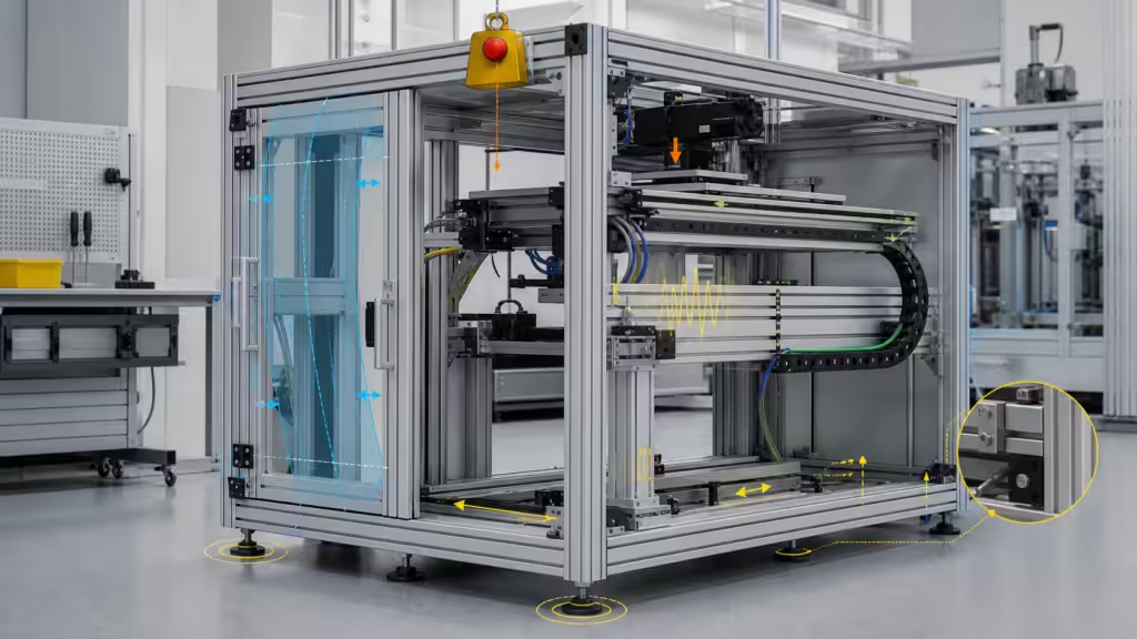
Before opening CAD, write a one-page design basis. This document prevents the project from quietly changing from “light sensor stand” to “operator leans on it while a robot stops hard” after the purchase order is issued.
Record these inputs:
- Overall envelope and keep-out zones
- Supported equipment mass and center of gravity
- Point loads, distributed loads, torque, and cantilever loads
- Acceleration, emergency-stop loads, vibration sources, and impact
- Required rail, camera, tool, or fixture alignment
- Maximum beam deflection and frame racking
- Column length, support condition, and anchoring method
- Guard panels, doors, interlocks, and access openings
- Temperature, humidity, chemicals, washdown, dust, and ESD needs
- Cable, pneumatic, coolant, and maintenance routes
- Expected reconfiguration and service life
- Applicable safety codes and customer standards
Separate strength limits from serviceability limits. Strength asks whether material, fasteners, and joints remain below allowable stress. Serviceability asks whether movement is small enough for the equipment to work. A vision system can fail its job long before an aluminum beam approaches yield. The camera is not impressed that the frame is technically still one piece.
Also define test conditions. A static proof load cannot by itself validate a frame exposed to repeated acceleration or vibration. A guard-door corner may need sag and cycle tests. A linear-axis support may need displacement measured at multiple positions across its travel.
Our documented development workflow uses a similar gated sequence: requirement definition, simulation, prototype manufacture, physical testing, data correction, process validation, and production release. In adjacent thermal-product programs, the internal deck reports that optimized design using Ansys, Fluent, and Flotherm shortened the development cycle by 50%. That is a documented workflow result, not a promise that every T-slot project will finish in half the time. The transferable lesson is simpler: solve expensive mistakes in the model and prototype before multiplying them in production.
How to calculate T-slot profile stiffness
Profile selection usually begins with beam deflection because excessive movement causes many practical failures. For a simply supported beam with a central point load, the basic elastic deflection is:
delta = F L^3 / (48 E I)
For a cantilever with an end load:
delta = F L^3 / (3 E I)
Here, F is load, L is span, E is elastic modulus, and I is the second moment of area around the bending axis. Support conditions and load distribution change the equation, so use the case that matches the real frame. The item technical data guide provides manufacturer guidance for determining profile deflection under different load arrangements.
Span matters more than intuition expects
Deflection scales with the cube of span. If the same beam and load double in span, its idealized deflection rises by a factor of eight. Adding one support can therefore do more than buying a much heavier profile. This is useful when a frame has room for a cross-member but the budget has begun making small coughing noises.
Orientation can change stiffness dramatically
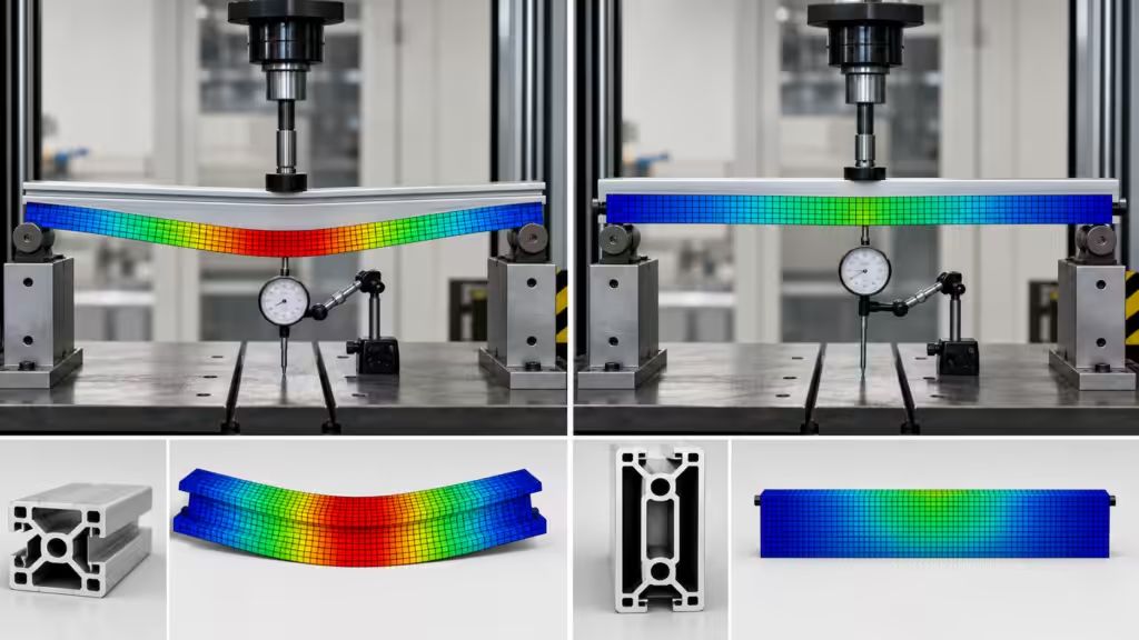
Rectangular profiles have different Ix and Iy values. Place the tall dimension in the primary bending direction when layout permits. One official 80/20 metric 80 x 20 mm profile lists Ix = 49.6609 cm4 and Iy = 3.7286 cm4. That is more than a 13:1 difference for the same piece of metal, depending on orientation. The values are specific to that 80/20 40-8020 profile, but the engineering lesson applies broadly.
Compare exact profiles, not series labels
A 40 x 40 mm example from the same supplier lists Ix = Iy = 7.8219 cm4, 6063-T6 material, and anodized finish. Those values belong to the specific 20-4040 cross-section. Another 40 x 40 profile with different wall thickness, core, or slot count may have different weight and inertia.
Do not copy a moment of inertia from an image that looks similar. Use the current datasheet, keep units consistent, and calculate around the loaded axis. A factor-of-10 unit error is remarkably efficient at converting a machine frame into modern dance.
Check more than beam bending
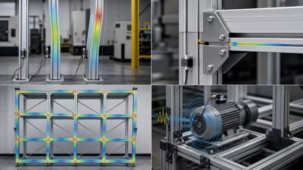
A useful structural review separates failure modes instead of hiding them inside one generous safety factor.
Beam stress and local loads
Calculate bending stress and combined loads where appropriate. Check concentrated loads near slots, end connections, tapped cores, access holes, and machined pockets. A globally stiff beam can still deform locally under a small bracket or narrow equipment foot.
Column buckling
Long uprights under compression may buckle before material strength becomes the limiting factor. Effective length depends on end restraint and bracing. Check both principal axes, especially for rectangular or partially closed profiles. Equipment mounted high on the frame may add bending moment as well as axial force.
Joint slip and rotation
Bolted T-slot joints rely on clamp force, contact friction, connector geometry, and local profile strength. Under-tightening can allow slip. Over-tightening can damage threads, deform the slot lips, or reduce repeatability. Use the connector supplier’s specified fastener, preparation, and torque. For critical joints, obtain tested load data or validate the assembly in the actual load direction.
Frame racking
A rectangular bay can distort into a parallelogram even when each member is strong. Add diagonal profiles, tension braces, gusset plates, rigid panels, or moment-resistant joints. Panel stiffness only counts if the attachment pattern can transfer shear into the frame.
Vibration and resonance
Static deflection is not a vibration analysis. Motors, pumps, fans, reciprocating tools, robot motion, and floor excitation can drive resonance. Increase stiffness, change mass distribution, shorten spans, add braces, isolate the source, or shift operating speed. Then measure the assembled frame, because a connector catalog cannot hear your machine humming.
T-slot profile sizes and configurations
Profile series help narrow a catalog, but series names are not a global performance standard. A “20 series” may refer to a 20 mm envelope in one system and a supplier family in another. Always pair the nominal size with the manufacturer, part number, slot type, wall class, weight per length, and section properties.
| Nominal metric envelope | Typical starting applications | Engineering checks |
|---|---|---|
| 20 x 20 mm | Sensor mounts, small enclosures, desktop fixtures | Short spans, low loads, connector availability |
| 30 x 30 mm | Light guards, test rigs, small workstations | Racking, door loads, accessory fit |
| 40 x 40 mm | Machine frames, automation cells, conveyor supports | Beam deflection, joint stiffness, anchoring |
| 40 x 80 mm | Bases, gantries, rail supports, long beams | Orientation, torsion, local rail interface |
| 45 mm and larger | Heavy frames and long-span structures | Mass, handling, connector capacity, TCO |
These are screening categories, not allowable-load recommendations. A braced 30 mm frame may outperform an unbraced 40 mm frame for lateral stiffness. A heavy-wall profile can improve section properties while preserving accessory compatibility, but it also adds cost and mass.
Open faces versus smooth faces
Slots on all faces maximize reconfiguration. Smooth or closed faces are easier to clean, improve appearance, and reduce places for debris to collect. Use only the slots the design needs. Covers can close unused channels, but they add parts and may not meet cleanroom or washdown requirements.
Square versus rectangular profiles
Square profiles simplify multi-directional framing. Rectangular profiles place more material away from one bending axis and can provide much higher stiffness where needed. They are useful below linear rails, across long machine openings, and in bases. Check torsion too, especially when the load acts away from the shear center or only one side of the beam is connected.
Light, standard, and heavy wall
Wall class affects inertia, weight, screw engagement, local bearing, and extrusion cost. Heavy is not automatically better. If the dominant problem is frame racking, one diagonal brace may outperform thicker walls. If the problem is local fastener pull-out, changing the connector may beat changing every meter of profile.
How T-slot connections work
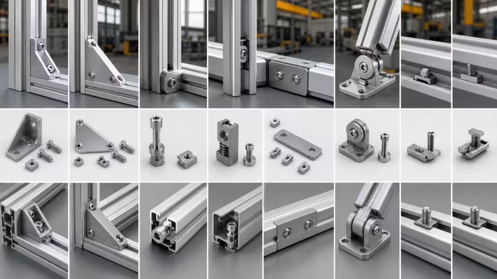
The connector controls assembly speed, access, appearance, adjustment, and much of the frame’s real stiffness. Choose it with the same seriousness as the profile.
| Connection | Best use | Advantage | Main limitation |
|---|---|---|---|
| External corner bracket | General 90-degree joints | Fast, visible, easy to inspect and reinforce | Occupies slot space and can obstruct panels |
| Gusset bracket | Loaded corners and bases | Better resistance to rotation and racking | Larger envelope and higher part count |
| End fastener | Clean profile-to-profile joint | Compact and economical | Requires end preparation and access |
| Internal anchor fastener | Clean exterior and repeated frames | Hidden hardware | Supplier-specific machining and installation |
| Joining plate | End-to-end or side reinforcement | Easy retrofit and broad load distribution | Uses external face area |
| Pivot joint | Adjustable arms and guards | Controlled angular adjustment | Requires positive locking for structural duty |
T-nuts also vary. Slide-in nuts enter from the profile end and often provide broad engagement. Roll-in or drop-in nuts can be added after the ends are blocked. Spring balls or leaf springs hold them in place during vertical assembly. The thread may be common; the body geometry may not be.
Use washers, thread locking, prevailing-torque features, or locking hardware only when the system supplier and application support them. Define whether joints must be removable. Mark critical fasteners after final torque so inspection can see movement. For repeated production, use a controlled tool and record the torque program rather than relying on one technician’s highly calibrated elbow.
The Bosch Rexroth Aluminum Structural Framing System catalog shows why connector selection must stay series-specific: its joining plates, slot sizes, dimensions, and hardware are organized around defined 30, 45, and 90 series interfaces.
Common engineering applications
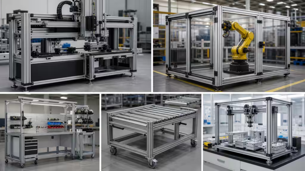
Machine frames and automation cells
T-slot framing suits equipment that changes during development or supports replaceable modules. Sensors, cameras, valves, cable trays, panels, actuators, and control enclosures can move without cutting the primary frame. For precision axes, use machined mounting plates or datum bars rather than expecting a raw slot face to serve as a perfect rail reference.
Machine guarding and enclosures
Profiles accept polycarbonate, sheet metal, mesh, and composite panels. They also support doors, hinges, handles, interlocks, and light curtains. In the United States, OSHA 29 CFR 1910.212 requires guarding methods that protect operators and other employees from hazards such as rotating parts, ingoing nip points, flying chips, and sparks. It also requires guards to be affixed to the machine where possible and not create hazards themselves. Review the actual OSHA machine-guarding requirement and the standards that apply to the specific machine.
The aluminum frame is only the perimeter. Safety depends on opening size, reach distance, panel retention, impact, door interlocking, bypass prevention, and the risk assessment.
Workstations and test benches
Adjustable shelves, monitor arms, footrests, tool rails, lights, bins, and power distribution make T-slot useful for ergonomic workstations. Set height and reach from the task. Check shelf deflection, caster capacity, stability, and the effect of pulling drawers or leaning on extended surfaces.
Conveyors, carts, and material handling
Modular profiles work well for conveyor stands, flow racks, carts, and transfer fixtures. Dynamic starts, stops, wheel impacts, uneven floors, and high centers of gravity deserve explicit load cases. For mobile frames, check caster mounting plates and braking forces.
Laboratories and controlled environments
Smooth anodized surfaces and removable panels support equipment enclosures and lab fixtures. Minimize exposed grooves where particles or liquids can collect. Specify compatible seals, cover strips, fasteners, and cleaning methods. A slot cover is useful, but it is not a cleanliness validation plan wearing a tiny plastic hat.
Are T-slot profiles from different brands compatible?
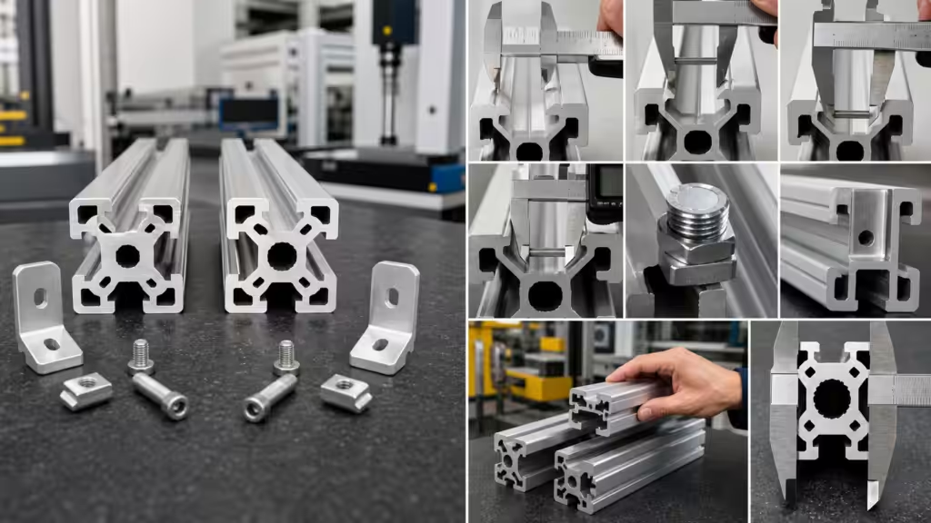
Sometimes, but nominal size alone is not proof. Metric and fractional systems should be treated as different families. Even within a metric envelope, suppliers can use different slot openings, depths, lip profiles, core holes, alignment features, and hardware.
Before mixing brands, compare:
- Profile envelope and corner radii
- Slot opening, internal width, depth, and lip thickness
- T-nut body width, engagement area, and insertion method
- Bolt thread, length, head clearance, and washer
- Center-bore diameter and tapping requirement
- Bracket alignment tabs and access-hole locations
- Panel groove, gasket, cover, hinge, and end-cap interfaces
- Finish thickness and electrical-contact needs
- Datasheet tolerance and inspection method
Then perform a physical fit test using parts from the production lots. Check insertion force, free sliding, rotation, seating, tightening, edge contact, and removal. Apply the real torque and load direction. A nut that enters the slot is not necessarily a nut that carries the design load.
For critical programs, section and measure representative samples. The Aluminum Extruders Council notes that standard and precision tolerances exist for straightness, flatness, twist, and dimensional features, and that requirements should be discussed with the extruder. Its extrusion tolerance guidance points designers to the relevant Aluminum Standards & Data tables.
Create an approved-components list by manufacturer and part number. If procurement substitutes a nut, bracket, or profile, repeat the interface check. “Looks about right” is not configuration management. It is the opening scene of a rework report.
When should you use a custom aluminum extrusion?
Standard T-slot profiles are best when speed, modularity, and broad accessory availability matter. A custom extrusion becomes attractive when repeated functions can be integrated into one constant cross-section.
Useful custom features include:
- Dedicated cable or pneumatic channels
- Integral panel tracks and sealing grooves
- Rail, sensor, or PCB mounting interfaces
- Smooth cleanable faces with slots only where needed
- Reinforcement concentrated around the real load path
- Custom screw bosses or captive-nut channels
- Thermal surfaces, ducts, or equipment interfaces
- Cosmetic faces and controlled assembly datums
Custom does not mean drawing every wish into one heroic cross-section. Die tongues need support. Wall thickness should remain balanced where possible. Sharp internal transitions, deep narrow cavities, wide thin sections, and large thickness changes can increase die stress, distortion, and cost. The Aluminum Extruders Council’s extrusion design tips recommend smooth transitions, practical radii, and ribs or grooves where they improve straightness and function.
Our internal catalog describes extrusion as suitable for high-volume production with low non-recurring engineering cost and most economical when post-machining is limited. That trade-off is central. If every length needs extensive milling, drilling, and manual fitting, the custom die may have integrated shape but not integrated cost.
A production-ready custom workflow
- Freeze interfaces, load cases, environment, annual volume, and acceptance criteria.
- Review the section with the extruder for die feasibility and tolerance.
- Calculate structure and local interfaces using supplier-confirmed properties.
- Prototype the risky joints, seals, panels, and machined datums.
- Approve finish and appearance samples.
- Inspect first articles for dimensions, straightness, twist, cut squareness, and fit.
- Validate the assembled module under representative load and environment.
- Release drawings, control plan, tooling, packaging, and revision records.
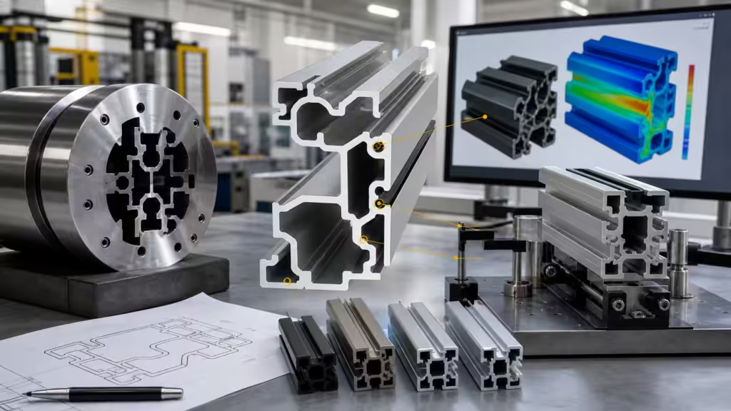
Manufacturing evidence that changes the specification
Good drawings define what matters and how it will be verified. Our internal production records provide several concrete examples from adjacent aluminum and thermal-hardware programs.
Machining envelope and first-article inspection
The capability deck lists a maximum machining size of 1,600 mm, tool-life control, multiple machine types, and FAI full-dimensional confirmation. For a T-slot order, that means long machined members need an agreed setup, datum strategy, access-hole position, end-tap depth, and measurement plan. The machine envelope does not prove every 1,600 mm feature can hold the same tolerance. It tells the project team what to confirm before release.
Test capacity and environmental validation
The same internal source lists 58 sets of professional test equipment, 2,000 m2 of laboratory space, and a 10-person test team. Its scope includes mechanical testing, rapid temperature change, thermal shock, humidity, random vibration, impact, high-temperature aging, and salt spray. Those capabilities come from thermal-product programs. They are relevant to harsh-environment frames only when the T-slot assembly receives its own test plan, fixtures, loads, and acceptance criteria.
Traceability and process control
The production deck records barcode traceability, automated flatness inspection, and MES monitoring of equipment parameters, process data, material history, quality results, scheduling, and ERP/PLM links. A modular frame program can use the same discipline for profile lots, cut lists, machined revisions, hardware kits, torque records, and nonconformance control.
Automated machining experience
Another internal catalog records vertical and 5-axis milling, turning, assembly, and plating. Its timeline states that automated palletized robots were added to 5-axis CNCs in 2023 for lights-out 24/7 machining, with further 5-axis equipment and robotics added in 2025. This is a machining automation record, not a T-slot frame case study. Its useful lesson is that fixtures, datums, part access, and repeatable blanks must be designed for automation rather than explained to the robot through optimism.
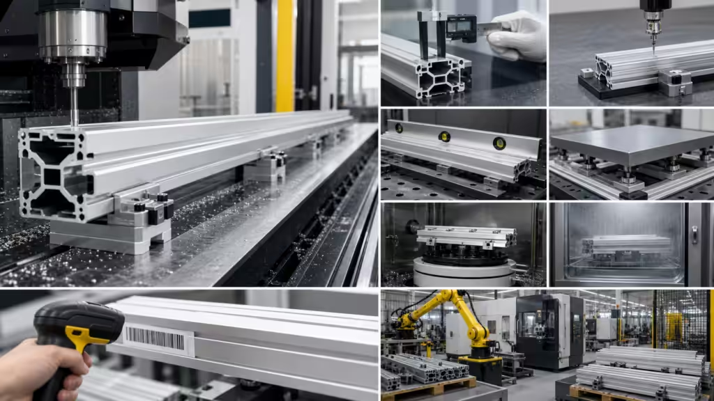
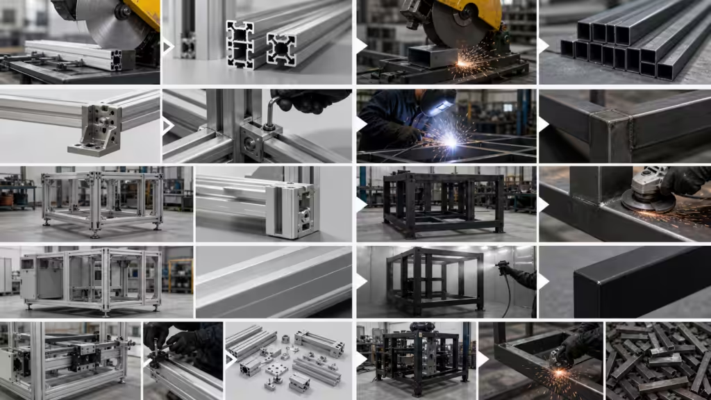
T-slot aluminum versus welded steel
T-slot aluminum usually costs more per kilogram than basic steel stock, while welded steel can provide very high stiffness and permanent joints. The correct comparison is the installed lifecycle cost for the actual structure.
| Cost element | T-slot aluminum | Welded steel |
|---|---|---|
| Material and hardware | Extrusion, connectors, fasteners, finish often included | Steel stock, weld consumables, coating system |
| Fabrication | Cutting, tapping, drilling, machining as required | Cutting, fixturing, welding, grinding, straightening |
| Assembly | Bolted, adjustable, basic tools | Skilled welding and controlled setup |
| Dimensional correction | Shims, adjustment, replaceable members | Heat distortion may require rework or machining |
| Modification | Loosen, move, add, or replace modules | Cut, weld, grind, refinish |
| Maintenance | Inspect joints, torque, damage, and finish | Inspect welds, corrosion, coating, and alignment |
| Reuse | High when lengths and hardware remain serviceable | Lower unless the frame can be cut and repurposed |
Do not use a universal percentage for labor savings. Build a project worksheet with local rates and measured times:
TCO = material + engineering + fabrication + assembly + finish + installation + validation + changes + maintenance - recovered reuse value
T-slot often wins for prototypes, frequently changed equipment, guards, workstations, and modular automation. Welded steel often wins for very heavy static structures, harsh impact, high-temperature exposure, tiny envelopes, or projects where permanent rigidity matters more than reconfiguration.
A hybrid frame can be best: welded or cast base for stiffness, machined datums for precision, and T-slot modules for guarding, sensors, controls, and future changes. Engineering is allowed to choose more than one material. The materials will not take it personally.
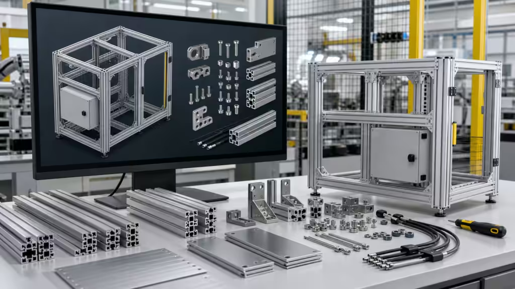
CAD, BOM, and procurement planning
Use supplier CAD models for profiles, connectors, nuts, covers, panels, hinges, feet, and fasteners. Confirm that the model revision matches the purchasable part. Manufacturer configurators can speed layout and BOM creation, but they do not replace structural calculations or risk assessment.
Build the frame as modules with defined interfaces. Give each cut member a unique identifier. Keep mating parts tied to common datums. Include fastener quantities, spare nuts, end caps, covers, anchors, panel gaskets, and installation tools in the BOM. Hardware omissions are cheap in CAD and remarkably expensive beside a stopped installation crew.
Your drawing package should state:
- Supplier, series, and profile part number
- Alloy, temper, finish, and appearance requirements
- Cut length tolerance and squareness
- Straightness, twist, flatness, and critical interface tolerances
- Hole, counterbore, slot, and end-tap datums
- Deburring and edge-break requirements
- Connector, fastener, thread, and torque specification
- Panel material, retention, gasket, and safety requirements
- Inspection level, FAI items, proof load, and functional tests
- Marking, packaging, revision, and substitution rules
For custom extrusions, review tolerances with the extruder before finalizing the drawing. A tighter number is not automatically a better number. It may require secondary straightening, machining, special gauges, lower process yield, or a price that causes procurement to stare silently into the middle distance.
How to assemble a T-slot aluminum frame accurately
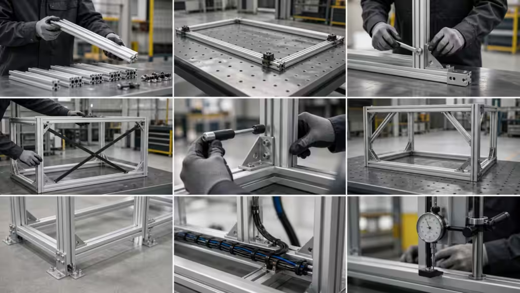
- Inspect incoming parts. Check part numbers, lengths, cuts, machining, finish, straightness, hardware, and accessory fit before assembly.
- Prepare a flat reference. Use a suitable table, fixture, or measured base. Floor unevenness can become frame twist.
- Preload hidden hardware. Insert slide-in nuts and internal connectors before closing profile ends.
- Build subassemblies loosely. Bring members into position without fully tightening every joint.
- Square and measure. Check diagonals, datums, levels, and critical mounting faces. Use temporary braces if needed.
- Tighten in sequence. Apply the supplier’s torque with a controlled tool. Recheck alignment as clamp loads build.
- Install permanent bracing and panels. Confirm that panels seat correctly and do not force the frame out of square.
- Anchor and level the frame. Follow the floor, machine, and anchor requirements. Recheck geometry after anchoring.
- Route services. Protect cables and hoses from sharp edges, motion, heat, and pinch points. Preserve service loops and access.
- Run acceptance tests. Measure proof-load deflection, racking, door operation, alignment, vibration, guarding, and fastener marks as required.
For repeat builds, create a fixture and an assembly control plan. Capture measured values rather than writing “looks square” in the traveler. If joints require a torque recheck after settling or transport, put that requirement in the installation instructions.
Common T-slot aluminum profile mistakes
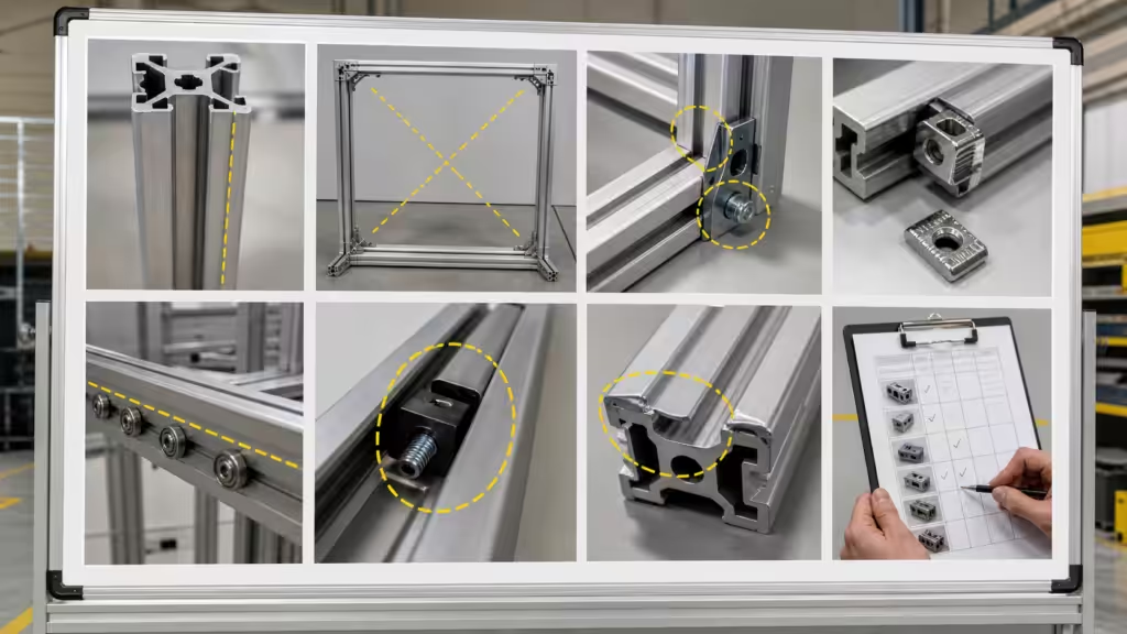
- Selecting by outside size instead of section properties
- Ignoring the weak axis of a rectangular profile
- Using strength as the only criterion when deflection controls function
- Assuming every joint is as rigid as the member
- Omitting diagonal bracing from tall rectangular bays
- Mixing metric, fractional, or cross-brand hardware without a fit test
- Mounting precision rails directly to unverified extrusion surfaces
- Blocking slide-in nuts before all accessories are installed
- Over-tightening fasteners and damaging slot lips or threads
- Letting doors, panels, and cable trays add unmodeled loads
- Skipping anchoring, floor checks, or mobile-frame stability
- Releasing production without FAI and a controlled cut list
Most of these errors are cheap to prevent. They become expensive after panels, wiring, sensors, and motion hardware are attached. The profile usually receives the blame because it is visible. The missing load case remains comfortably anonymous.
Frequently asked questions
What is the best alloy for T-slot aluminum profiles?
6063-T6 is common because it combines extrudability, finish quality, corrosion resistance, and useful mechanical properties. Use the alloy, temper, section properties, and allowable data specified by the profile supplier. Do not substitute generic alloy values for the selected product.
Is a 40 x 40 profile stronger than a 30 x 30 profile?
Usually, a larger section has greater stiffness and load capacity, but the answer depends on wall design, slot count, alloy, span, orientation, support, joints, and load direction. Compare the exact part numbers and Ix, Iy, section modulus, weight, and connector data.
How much weight can a T-slot aluminum profile hold?
There is no universal load. Capacity depends on span, support condition, load position, deflection limit, orientation, profile properties, joint design, buckling, frame bracing, and safety factors. Calculate the actual load case and verify critical assemblies.
Can T-slot aluminum replace welded steel?
It can replace welded steel in many machine frames, guards, workstations, test rigs, and modular automation systems. Welded steel may remain better for very heavy, high-impact, high-temperature, compact, or permanently rigid structures. Hybrid construction is often practical.
Can I mix T-slot profiles and hardware from different brands?
Only after comparing slot geometry, fasteners, connector tabs, center bores, tolerances, and finish, followed by a physical fit and load-relevant test. Matching nominal sizes do not guarantee compatibility.
Do T-slot frames need diagonal bracing?
Tall or laterally loaded rectangular bays often do. Gussets, rigid panels, moment-resistant joints, and anchors can also resist racking. The complete frame geometry and joint stiffness determine the requirement.
When is a custom T-slot extrusion worth the tooling cost?
Custom extrusion makes sense when it repeatedly removes brackets, machining, covers, cable trays, seals, assembly steps, or performance compromises. Compare tooling and qualification cost with annual volume and recurring savings.
Final engineering checklist
Before ordering, confirm:
- Loads, movement limits, environment, safety requirements, and service access are documented.
- The exact profile supplier, part number, revision, and section properties are approved.
- Beam deflection, stress, column buckling, joint behavior, racking, and vibration are checked where relevant.
- Profile orientation, supports, braces, panels, anchors, feet, and casters are included in the model.
- T-nuts, brackets, fasteners, hinges, covers, and gaskets have verified compatibility.
- Custom cuts and machining use functional datums and realistic tolerances.
- FAI, fit checks, proof loads, and functional acceptance tests are defined.
- BOM, cut list, torque values, spare hardware, marking, packaging, and revision control are complete.
- Future modules can be added without blocking safety, access, or the primary load path.
T-slot aluminum profiles are powerful because they let a structure evolve. That flexibility works best when the first version has honest load cases, supplier-specific data, measured joints, and a production plan. Modularity is not permission to skip engineering. It is permission to change the engineering without reaching for an angle grinder.
For related extrusion fundamentals, read Why Extruded Aluminum Heat Sinks Outperform Others. For a closer look at AL6063 and extrusion trade-offs, see Aluminum Heatsinks: Types, Function, and Efficiency Explained.
We support custom aluminum extrusion, CNC machining, surface finishing, prototyping, dimensional inspection, and engineering validation. Send the frame envelope, loads, spans, equipment interfaces, environment, preferred series, annual volume, and CAD files. Those inputs are enough to begin a useful DFM review instead of quoting a rectangle and discovering the machine later.