
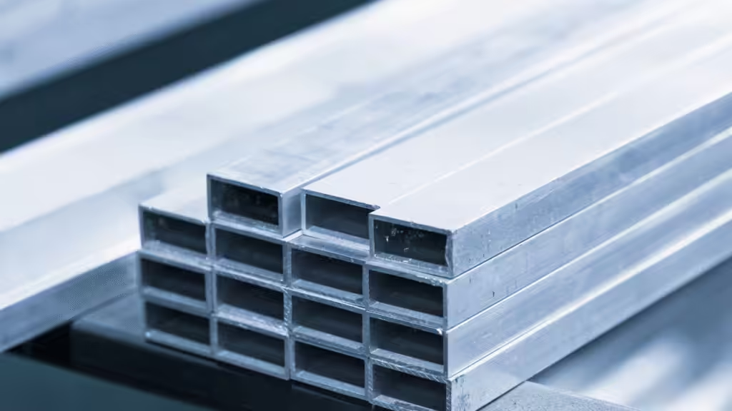
Choosing the best T-slot aluminum profile system is not a contest to find the chunkiest extrusion in the catalog. You are choosing a complete interface: profiles, joints, T-nuts, panels, machining options, documentation, and replacement parts must all cooperate after the CAD model leaves its comfortable digital habitat.
The wrong choice rarely announces itself with cinematic collapse. More often, a rail drifts out of alignment, a guard door sags, a corner slips, or a discontinued nut turns a five-minute repair into industrial archaeology.
We use a requirements-first process: define the loads and allowed movement, compare supplier-specific engineering data, verify every critical interface, and test the first assembly. This guide turns that process into a practical selection method for machine frames, guards, workstations, fixtures, carts, and automation cells.

Quick Answer: Which T-Slot Aluminum Profile System Should You Choose?
Choose the T-slot aluminum profile system that meets your real load, stiffness, interface, environmental, and service requirements using data for the exact profile and connector combination. The best system is not a universal brand or series. It is the smallest complete system you can calculate, assemble, source, inspect, and modify without creative profanity.
Use this sequence:
- Define the job. Record the frame envelope, equipment mass, load positions, acceleration, vibration, guarding, access, and expected modifications.
- Set performance limits. Specify allowable beam deflection, rail misalignment, frame racking, joint movement, and door sag before selecting a profile.
- Choose structure or motion. Use T-slot for modular structural framing. Consider V-slot for light integrated wheel motion, or mount dedicated linear guides on a T-slot frame for higher precision and load.
- Calculate the members. Check the exact section properties, span, orientation, support condition, bending, buckling, torsion, and local loads.
- Design the joints and braces. The extrusion does not carry the machine by telepathy. Brackets, fasteners, panels, anchors, and diagonal members must complete the load path.
- Verify the ecosystem. Confirm slot geometry, T-nuts, connectors, hinges, feet, panels, covers, CAD files, stock, machining, and replacement-part availability.
- Approve a first assembly. Inspect the parts, build the highest-risk bay, apply controlled torque, and measure the behavior that matters before releasing the full order.
| Application | Sensible starting point | What decides the final choice |
|---|---|---|
| Sensor stand or small desktop fixture | Compact 20 or 30 mm family | Short-span deflection, mounting space, accessory fit |
| Machine guard or light workstation | 30 or 40 mm family | Bay bracing, door load, anchoring, panel attachment |
| Automation cell or machine base | 40 mm or larger structural family | Dynamic loads, joint stiffness, racking, vibration |
| Long beam or linear-rail support | Rectangular or heavy profile | Loaded-axis inertia, torsion, rail alignment |
| Moving gantry | V-slot or separate linear-guide system | Accuracy, speed, wheel or bearing load, wear |
| Repeated product with crowded interfaces | Standard system or custom extrusion | Annual volume, machining content, tooling, lifecycle cost |
These size families are screening categories, not load ratings. A well-braced 30 mm frame may resist lateral movement better than an unbraced 40 mm rectangle, while a badly oriented rectangular beam can make an expensive profile perform like a budget ruler.
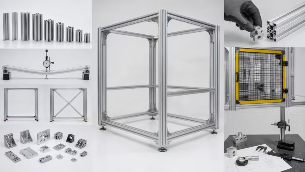
1. Define What the Frame Must Actually Do
Profile selection starts with a one-page design basis, not a catalog tab left open beside your CAD window. Write down what the structure supports, how it moves, where it is restrained, and how much movement the equipment can tolerate.
Our internal development workflow follows the same basic order for manufactured products: requirements, simulation, prototype testing, design correction, process validation, and production preparation. That sequence matters here because a larger extrusion can hide a weak assumption, but it cannot fix one.
Separate Structural Framing from Linear Motion
A T-slot profile is primarily a structural member and mounting interface. Its slots accept connectors and accessories anywhere along the length. This makes it useful for frames that must change without cutting and welding.
A structural profile is not automatically a motion guide. If a carriage must travel along the beam, define the required accuracy, speed, load, duty cycle, and wear life. Light V-wheels may run directly on a V-slot. Industrial axes often need a separate linear rail mounted to a stiff T-slot beam.
Record Static, Dynamic, Accidental, and Service Loads
List every load the finished structure can see:
- Equipment mass, workpieces, panels, doors, and stored material
- Point loads, distributed loads, cantilevers, and applied torque
- Motor reaction, robot acceleration, emergency stops, and reciprocating tools
- Operator contact, cart impact, cable forces, and maintenance loads
- Repeated cycles, floor vibration, and transport loads
Record each load’s position and direction. A 50 kg machine centered over four uprights creates a different problem from the same mass hanging 400 mm beyond one beam. Gravity has no loyalty to your BOM.
Set Limits for Deflection, Vibration, Racking, and Alignment
Strength and serviceability are separate checks. Strength asks whether the material, fasteners, and joints remain within allowable limits. Serviceability asks whether the frame stays accurate enough to do its job.
Set numerical limits for beam deflection, rail straightness, camera movement, door sag, and bay racking. Also define acceptable vibration at sensitive equipment. A frame can remain far below yield stress while moving enough to ruin an inspection result or make a sliding door develop opinions.
Include Guarding, Access, Services, and Future Changes
Add panels, hinges, interlocks, leveling feet, anchors, cable trays, air lines, covers, and maintenance clearances to the design basis. These parts consume slot space and change load paths. A bracket that looks elegant in CAD becomes less charming when a polycarbonate panel blocks the hex key.
State where future equipment may be added and which members should remain reusable. If the frame is a safety guard, apply the relevant machinery-safety requirements for the installation location. In the United States, OSHA 1910.212 requires guarding methods that protect operators from machine hazards; choosing aluminum profiles does not replace the guarding risk assessment.
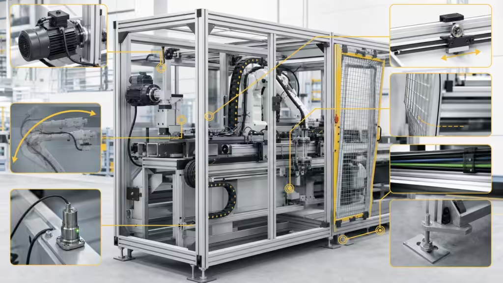
2. T-Slot vs. V-Slot: Choose Structure, Motion, or a Hybrid
T-slot and V-slot profiles can share similar outer dimensions, but their working interfaces solve different problems. T-slot captures nuts and connector heads for structural assembly. V-slot presents angled running surfaces for compatible wheels.
| Decision factor | T-slot profile | V-slot profile |
|---|---|---|
| Primary role | Structural framing and mounting | Integrated light-duty linear motion |
| Typical hardware | T-nuts, brackets, anchors, panels | V-wheels, eccentric spacers, plates |
| Structural ecosystem | Broad range of sizes and connectors | Usually narrower and motion-focused |
| Motion accuracy | Uses added linear guides or bearings | Depends on wheel fit, preload, and wear |
| Best-fit examples | Machine bases, guards, fixtures, workstations | 3D printers, camera sliders, light gantries |
When T-Slot Is the Better Choice
Choose T-slot when the main requirement is a rigid, adjustable structure. Its accessory ecosystem makes it easier to mount guards, sensors, actuators, work surfaces, feet, and custom plates. Larger rectangular sections and heavy connectors are also widely available for long beams and machine bases.
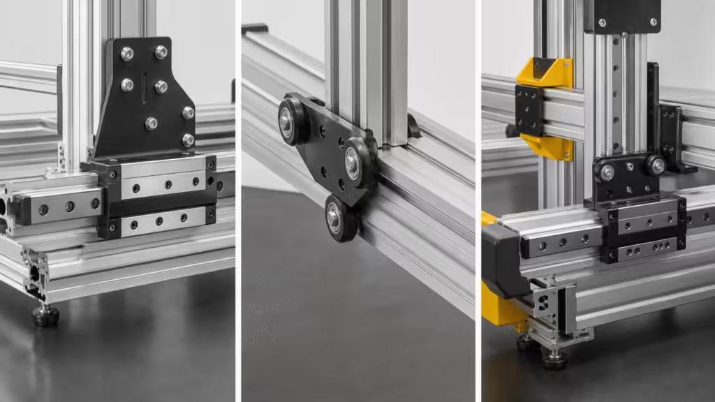
For precision motion, treat the T-slot frame as the support. Mount a profiled linear rail, bearing shaft, or other purpose-designed guide to a prepared datum. Then calculate how frame deflection and joint movement affect that guide.
When V-Slot Integrated Motion Makes Sense
Choose V-slot when the angled groove can serve as the wheel track. Confirm that the load, speed, contamination, precision, and service life suit that approach. It can reduce part count in light motion systems because one extrusion performs two jobs.
That convenience has limits. Wheel preload changes with assembly and wear. Debris can reach the running surface. A profile that works well for a desktop axis may be a poor foundation for a heavy industrial gantry.
When to Combine Both Systems
A hybrid design can use T-slot for the static frame and V-slot for a light moving carriage. Another common hybrid uses T-slot framing with bolted linear rails. In either case, design an adapter interface rather than assuming the grooves, nuts, or bracket tabs will cooperate.
Base the choice on the primary function. If the system’s job is to hold geometry, start with T-slot. If its job is to guide wheels, assess V-slot. If it must do both under demanding loads, separate the structural and motion functions so each can be verified.
3. Choose the Profile Size with Engineering Data
Profile size should follow the load path and movement limit. Outer dimensions are useful for filtering a catalog, but the calculation needs the exact cross-section, alloy state, section properties, mass per length, and orientation.
Use the Exact Manufacturer Datasheet
Download the current datasheet and CAD model for the exact part number. Record:
- Cross-sectional area and mass per length
- Second moment of area, usually listed as
IxandIy - Section modulus around both axes
- Torsional properties when the supplier provides them
- Alloy, temper, finish, straightness, and dimensional tolerances
- Slot geometry, center bore, and permitted machining
Do not borrow values from a visually similar profile. Two 40 x 40 mm extrusions can have different walls, cores, and slot counts. The aluminum does not care that the thumbnails looked related.
Calculate Beam Deflection for the Real Load Case
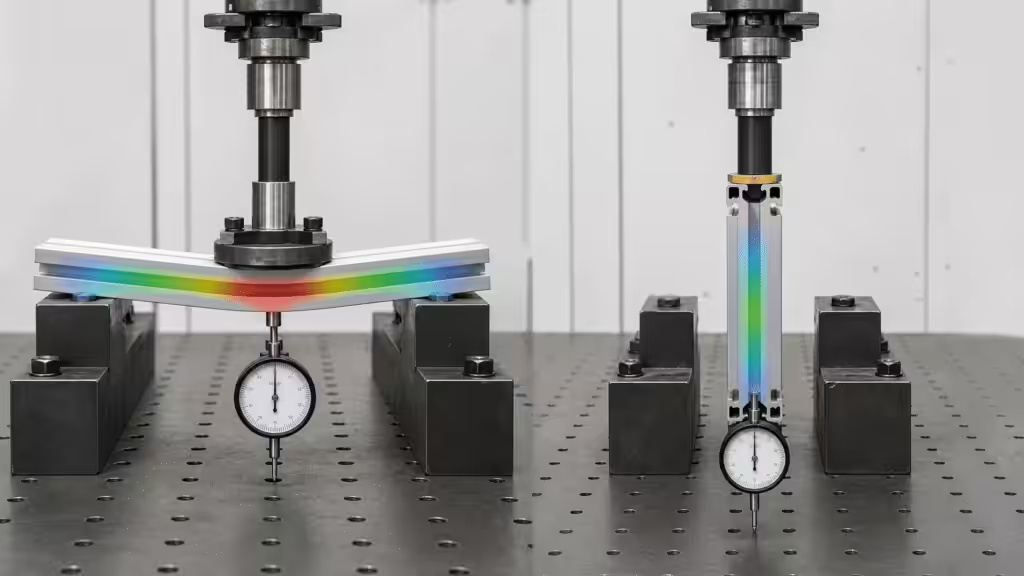
For a simply supported beam with a central point load, the ideal elastic deflection is:
delta = F L^3 / (48 E I)
For a cantilever with an end load:
delta = F L^3 / (3 E I)
F is load, L is unsupported span, E is elastic modulus, and I is the second moment of area around the loaded axis. Use the equation for the real support and load arrangement. The official item profile technical guide provides supplier guidance for profile deflection under several load cases.
Span appears to the third power. Double the span while holding everything else constant and the idealized deflection rises eightfold. Before upgrading every beam, ask whether one well-placed support can shorten the critical span.
Check the Strong and Weak Bending Axes
Rectangular profiles behave very differently in their tall and flat orientations. Select Ix or Iy to match the bending direction. Put the taller dimension in the primary bending plane when the envelope and interfaces allow it.
Check secondary loads too. A rail mounted off-center can twist the beam. A motor plate may add torque and local wall deformation. If the main load changes direction during operation, calculate both axes rather than choosing the friendlier number.
Review Column Buckling, Torsion, and Local Loads
Long uprights under compression may buckle before the alloy reaches its compressive strength. Effective length depends on end restraint and bracing, so check both principal axes and the real column condition.
Also review torsion, local bearing below brackets, fastener pull-out, tapped-core engagement, and stress around machined holes. A strong beam can still fail at a narrow equipment foot or over-machined connector pocket.
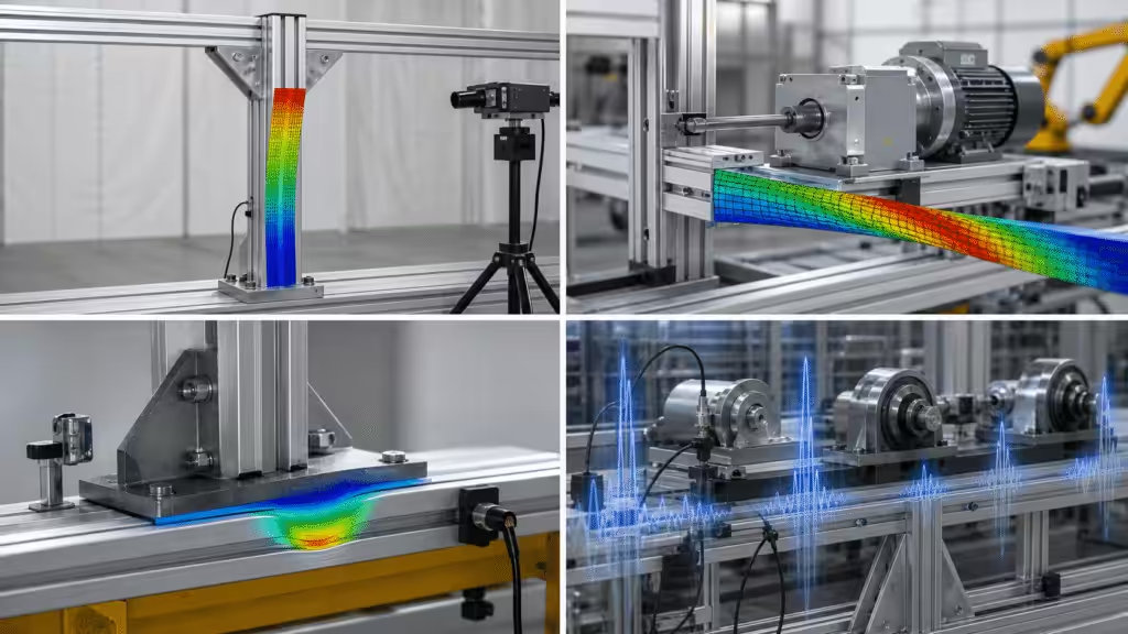
Dynamic equipment adds another check. Static stiffness does not predict resonance. Motors, robots, pumps, and reciprocating tools can excite the assembled frame. Change span, bracing, mass, isolation, or operating speed, then measure the prototype.
Why Series Names Are Not Strength Ratings
Names such as 20, 30, 40, or 45 series usually describe a supplier’s dimensional family. They do not create a cross-brand structural standard. Even within one family, light, standard, heavy, smooth-face, and multi-slot versions can have different section properties.
Use the series name to find compatible products. Use the part-number data to approve performance.
4. Evaluate the Connection System, Not Just the Extrusion
The frame is a network of members and joints. A large profile connected with a flexible corner can move more than a smaller profile with a properly braced load path. Select the connector for load direction, stiffness, access, adjustment, appearance, and repeatability.
Brackets, Gussets, Anchors, and End Fasteners
| Connection method | Useful for | Main trade-off |
|---|---|---|
| External corner bracket | General 90-degree joints and prototypes | Fast to fit but occupies face and slot space |
| Gusset bracket | Loaded corners, bases, and open bays | Better rotational restraint with a larger envelope |
| End fastener | Compact profile-to-profile joints | Requires end preparation and tool access |
| Internal anchor | Clean outer faces and repeated builds | Often supplier-specific and machining-dependent |
| Joining plate | Reinforcement or retrofit | Easy to inspect but consumes mounting area |
| Pivot joint | Adjustable arms and guards | Needs positive locking for structural duty |
Choose hardware with tested capacities for the chosen profile where possible. Connector ratings must match the load direction and assembly method; a pull-out result is not automatically a moment rating.
The official Bosch Rexroth aluminum structural framing catalog organizes profiles, joining plates, fasteners, and dimensions around defined system families. That is a useful reminder to keep connector data tied to its original series.

Joint Slip, Rotation, and Fastener Torque
T-slot joints depend on clamp force, friction, connector geometry, bolt strength, thread engagement, and local profile stiffness. Under-tightening can permit slip. Excess torque can strip threads, crush slot lips, or distort a bracket.
Follow the system supplier’s fastener preparation and torque instructions. Do not publish a universal torque table assembled from unrelated brands. For repeated production, use a controlled tool and mark or record critical joints after final tightening.
Bracing Rectangular Bays
A rectangular bay can rack into a parallelogram even when every beam passes its bending check. Add diagonal profiles, tension braces, gusset plates, rigid shear panels, or joints designed to resist moment.
Do not count a panel as structural bracing unless its material, edge distance, attachment spacing, fasteners, and load transfer have been designed for that job. Four clips and optimism are not a shear wall.
Plan Assembly and Maintenance Access
Model the tools and hands required for assembly. Check whether panels block bolt heads, a wall prevents end-loading T-nuts, or a hidden anchor becomes unreachable after the next beam is installed.
Define an assembly sequence. Use roll-in nuts where ends will be blocked and slide-in nuts where broad engagement or controlled placement is required. Leave access for re-torque, sensor replacement, panel removal, and later expansion.

5. Verify Slot and Accessory Compatibility
Profiles with the same nominal envelope may belong to incompatible ecosystems. The slot is a mechanical interface, so approve it with dimensions and a physical sample rather than a series nickname.
Measure the Slot Geometry
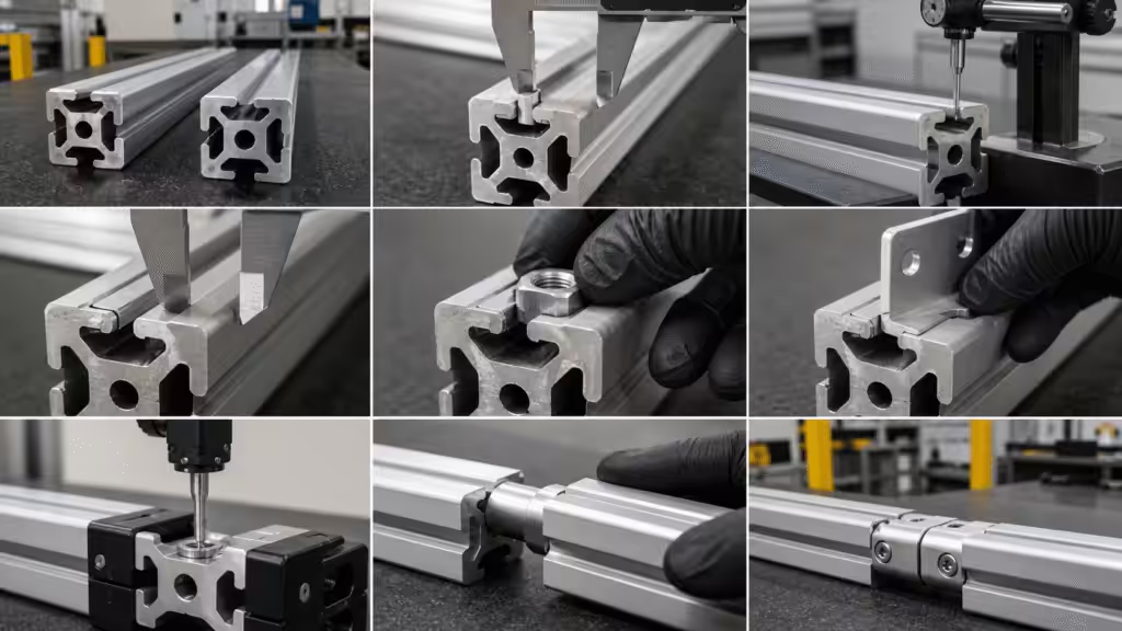
Measure the slot opening, internal width, depth, lip thickness, corner shape, and distance from the profile face to the nut-bearing surface. Check the center bore if the design uses end taps or core fasteners.
Then measure the mating hardware. A nut must enter as intended, rotate or seat correctly, develop enough bearing area, and remain captured under service loads. Bracket tabs must fit the external grooves without holding the bracket away from the profile face.
Choose Slide-In or Roll-In T-Nuts
Slide-in T-nuts enter from an open profile end. They often provide generous engagement and predictable orientation, but the assembly sequence must keep an end accessible.
Roll-in or drop-in nuts can be added after the frame is partly built. Springs, balls, or leaf features can hold them during vertical assembly. They are useful for retrofit work, but the insertion path and final engagement must match the exact slot.
Hammer nuts may be convenient for light accessories. Do not quietly promote them to structural fasteners because the preferred nut was out of stock.
Audit the Accessory Ecosystem
A useful system needs more than straight profiles. Check the available:
- Structural brackets, anchors, joining plates, and base feet
- Nuts, bolts, washers, thread sizes, and locking options
- Hinges, latches, handles, panel retainers, and safety accessories
- Slot covers, cable clips, seals, end caps, and leveling hardware
- CAD models, technical drawings, load data, and assembly instructions
- Cut-to-length, drilling, tapping, milling, and kitting services
Also check stock depth and product-change policy. A perfect hinge that arrives in twelve weeks is an interesting sculpture, not a production component.
Run a Physical Cross-Brand Fit Test
For mixed-brand hardware, obtain short profile samples and representative nuts, brackets, covers, and panel seals. Use calipers or an optical system to record the interfaces, then build the connection and inspect seating, tool access, and thread engagement.
For loaded joints, run a test in the actual force direction. Record the fastener, torque, setup, displacement, slip point, and visible damage. The goal is not to prove that two parts can be persuaded into the same room. It is to prove they form a repeatable joint.
6. Select Alloy, Temper, and Surface Finish
Alloy and finish affect extrusion quality, corrosion behavior, appearance, machining, and electrical interfaces. They do not replace section-property or joint calculations.
Why 6063-T6 Is Common
6063-T6 is common in modular framing because 6063 can form detailed extruded cross-sections, accepts anodizing well, and offers a practical strength-to-weight balance. The Aluminum Association’s standards resources explain the industry’s alloy and temper designation system; the exact mechanical values still come from the selected product specification.
Our manufacturing catalog uses Aluminum Alloy 6063 for both standard and custom extruded thermal products. That is direct experience with the extrusion process and finish options, but it is not a structural rating for a T-slot frame. Require the profile supplier to state the actual alloy, temper, tolerances, and section properties.
What Anodizing Does and Does Not Solve
Anodizing grows a controlled oxide layer on the aluminum surface. It improves corrosion resistance, wear behavior, and finish consistency. Suppliers may offer clear, black, or custom colors; our catalog, for example, lists custom anodize colors for custom extrusions.
Anodizing does not guarantee color matching between production lots. It does not protect a fresh cut to the same degree as an anodized face. It can also interrupt electrical continuity through a bolted joint and affect tight fits. Define whether critical dimensions apply before or after finishing.
Check Corrosion, Grounding, ESD, and Cleaning Requirements
Specify the real exposure: indoor factory air, humidity, salt, cleaning chemicals, coolant, washdown, abrasive dust, or outdoor weather. Review galvanic contact when aluminum meets stainless steel, carbon steel, copper, or carbon-fiber components, especially in the presence of an electrolyte.
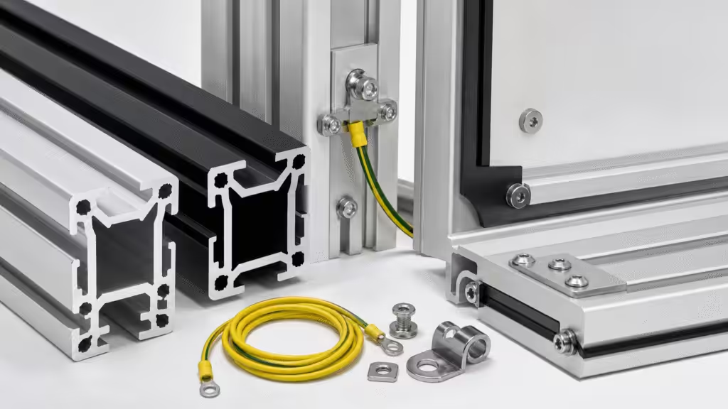
If the frame needs protective earth or ESD control, design dedicated bonding points. Remove or penetrate insulating finishes only through an approved process, use suitable hardware, and verify continuity after assembly and maintenance.
For clean areas, compare open slots with smooth faces and removable covers. Covers can reduce debris traps, but they add parts and seams. In washdown service, examine drainage, crevices, panel seals, fastener materials, and whether the chosen framing system was actually designed for that environment.
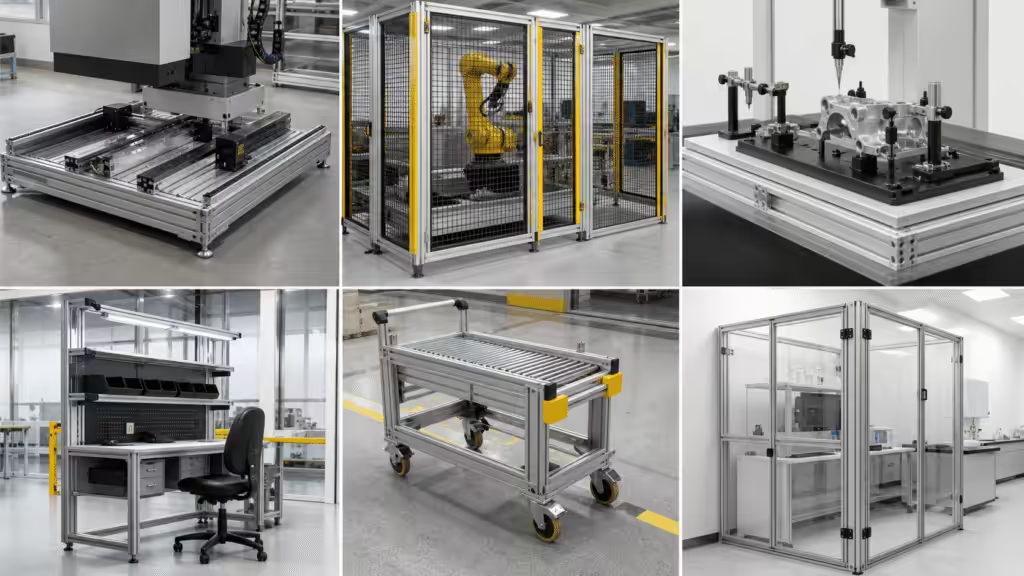
7. Match the System to the Application
The best system changes with the failure mode that matters most. Use the application to identify the dominant load, interface, environment, and service task before comparing product families.
Machine Frames and Automation Cells
Machine frames need predictable stiffness under equipment weight and operating forces. Check long beams, motor torque, robot acceleration, anchoring, and vibration. Use gussets or braces where open bays could rack.
For linear rails, choose a beam with adequate loaded-axis inertia and torsional stiffness. Define the rail-mounting datum and machining method. The continuous slot is useful for adjustment, but it is not a substitute for a straight, controlled mounting surface.
Safety Guards and Access Doors
Guards often carry light static loads, yet doors create concentrated and repeated loads at hinges and latches. Check door sag, latch alignment, cycle life, panel retention, base anchoring, and the force an operator may apply.
Choose profiles and covers that reduce sharp edges and pinch points. Integrate interlocks and cable protection without leaving bypass-friendly gaps. Guard geometry and strength must come from the machine risk assessment, not from how reassuring the silver frame looks.
Precision Fixtures and Inspection Rigs
Fixtures and inspection rigs care about repeatable geometry. Set limits for movement at locators, cameras, probes, and sensors. Use dedicated datums or machined plates where adjustment must be repeatable after service.
Adjustable joints are helpful during development. Once the setup is approved, add location features, controlled torque, witness marks, or hard stops so the next build does not depend on one technician’s memory.
Workstations, Carts, and Conveyor Supports
Workstations prioritize ergonomics, accessory placement, and later adjustment. Check work-surface loads, monitor and tool arms, foot clearance, leveling, and stability when drawers are open.
Carts add caster loads, thresholds, impacts, and a moving center of gravity. Conveyor supports add belt tension, drive reaction, accumulation loads, and alignment requirements. For both, check the whole assembly against tipping and racking rather than approving each beam in isolation.
Clean or Harsh Industrial Environments
Smooth faces, sealed joints, and suitable fasteners may matter more than maximum slot access in clean or wet service. For harsh environments, evaluate corrosion, chemical exposure, drainage, debris collection, temperature, and inspection access.
| Application | Primary checks | Useful system features |
|---|---|---|
| Machine base | Deflection, vibration, anchoring | Rectangular beams, heavy joints, leveling feet |
| Robot guard | Racking, door cycles, safety gaps | Braces, panel channels, interlock mounts |
| Inspection fixture | Alignment, repeatability, thermal drift | Machined datums, adjustment hardware, low-slip joints |
| Workstation | Ergonomics, stability, accessory changes | Broad hardware ecosystem, adjustable feet |
| Mobile cart | Impact, caster loads, tipping | Base plates, locking casters, diagonal bracing |
| Clean or wet area | Crevices, drainage, corrosion | Smooth faces, covers, seals, compatible fasteners |
8. Compare Total System Cost
Compare systems at the finished-frame level. Extrusion price per meter is easy to quote and easy to misuse because the frame also needs engineering, cuts, holes, connectors, panels, labor, inspection, packaging, and future service.
Price the Finished Frame, Not the Extrusion Meter
Build a costed BOM that includes:
- Profiles, scrap allowance, and minimum order quantities
- Brackets, nuts, bolts, anchors, feet, and covers
- Sawing, deburring, drilling, tapping, and milling
- Panels, doors, seals, labels, and safety hardware
- Assembly labor, tools, jigs, and inspection
- Packaging, freight, installation, and spares
A lower-cost profile can produce a higher-cost frame if it requires more machining or connectors. A premium system may earn back part of its price through better documentation, stocked hardware, or cut-and-kit service. Calculate it; do not let the brochure calculate it emotionally.
Include CAD, BOM, Stock, and Replacement-Part Costs
Good CAD models reduce interface errors and engineering time. Clear part numbers and configurable BOMs reduce purchasing mistakes. Reliable stock and long-term replacement parts reduce downtime after the machine ships.
Include the cost of change. Ask how easily the team can add a sensor, widen a guard, replace a damaged member, or reuse profiles in the next revision. Also price the risk of supplier-specific hardware becoming unavailable.
Our manufacturing records treat BOM control, first-article inspection, traceability, and revision control as distinct production tasks. They belong in the T-slot system budget too. A prototype assembled from unlabeled cut lengths may work once; repeating it ten times is where the invoice develops subplots.
Compare T-Slot Framing with Welded Steel
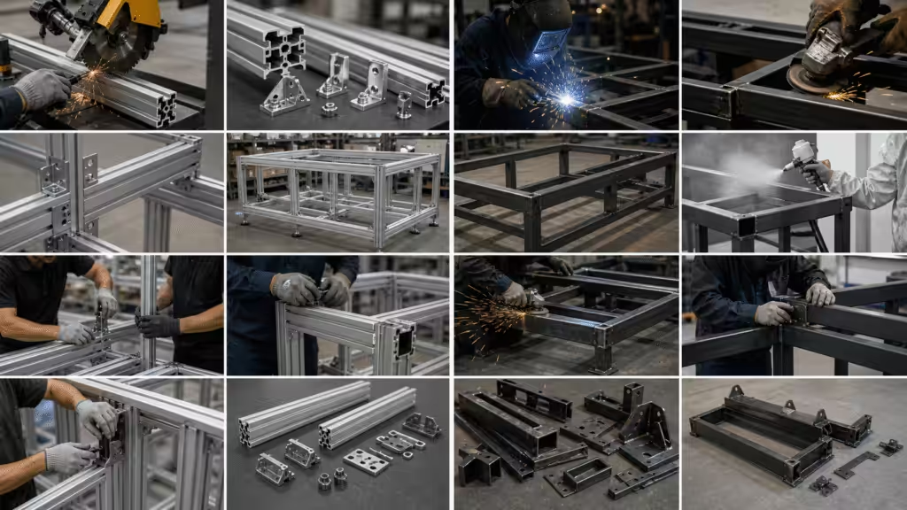
T-slot aluminum usually favors fast, clean assembly and reversible changes. Welded steel often favors high rigidity, compact joints, locally reinforced structures, and material cost efficiency at larger loads.
| Decision factor | T-slot aluminum framing | Welded steel framing |
|---|---|---|
| Initial assembly | Bolted with ordinary shop tools | Cutting, fixturing, welding, and finishing |
| Heat distortion | None from assembly | Must be managed during welding |
| Modification | Usually reversible | Often requires cutting and rework |
| Joint stiffness | Depends on connectors and clamp | Can be high with designed welds and gussets |
| Corrosion finish | Commonly supplied anodized | Usually needs coating or other protection |
| Reuse | Members and accessories can be reused | Reuse is more difficult |
| Heavy compact structure | Can become bulky or expensive | Often advantageous |
Neither method wins every project. Compare the required stiffness, envelope, volume, available skills, finish, delivery time, and expected changes. A hybrid frame can use welded steel where mass and stiffness are useful, with T-slot members for guards and adjustable interfaces.
9. Standard Profile or Custom Extrusion?
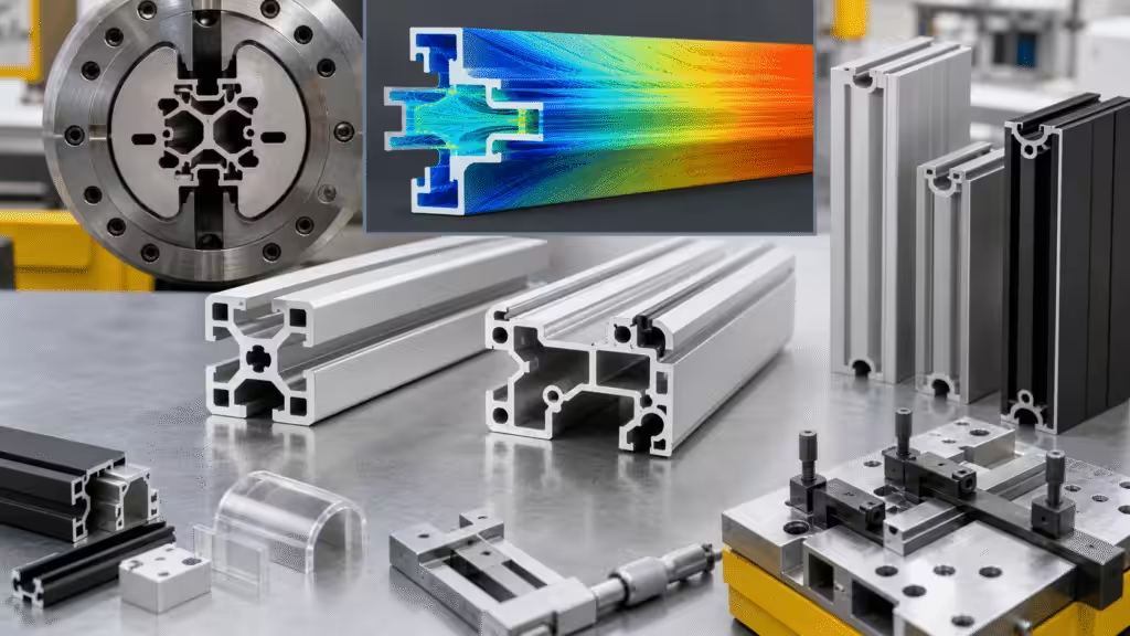
A standard system should be the default because it provides tested interfaces, stocked hardware, and shorter development work. A custom extrusion becomes attractive when repeated builds can remove meaningful parts, machining, space, or assembly risk.
When a Catalog System Is Enough
Stay with a catalog profile when the structure is low volume, likely to change, or well served by existing slots and accessories. Standard profiles are also safer when field replacement and global availability matter.
Use custom brackets and plates to solve isolated interfaces before redesigning the extrusion. CNC parts can add datums, motor mounts, bearing seats, and sensor locations while the standard frame remains easy to modify.
When Repeated Builds Justify a Custom Cross-Section
Consider a custom cross-section when the same assembly repeats and several of these conditions apply:
- Standard profiles waste envelope or material
- Multiple covers, brackets, or channels can become one feature
- Cable, airflow, sealing, or panel interfaces repeat along the full length
- A dedicated datum can reduce alignment work
- Part-count reduction offsets tooling and qualification effort
- Forecast volume and product life support the investment
Our extrusion catalog describes extrusion as suitable for high-volume production with low non-recurring engineering cost and most cost-effective when post-machining is not required. That evidence comes from thermal-product manufacturing, so it does not set a universal T-slot volume threshold. It does capture the central trade-off: the die earns its keep when the cross-section performs useful work along most of the length.
Integrate Channels, Grooves, Datums, and Screw Bosses
A functional custom profile can combine selective T-slots with cable channels and panel-seal grooves. It can also include screw bosses, locating features, smooth faces, or a rail-mounting datum. Keep the cross-section manufacturable. Use consistent walls where practical, realistic radii, supported features, and enough access for finishing and inspection.
For more detail on tooling, flow, aspect ratios, and post-machining, read Why Extruded Aluminum Heat Sinks Outperform Others. The product is different, but the extrusion process constraints still apply.
Review the design with the extruder before freezing CAD. Die flow, tongue strength, distortion, quench response, straightness, twist, and anodizing can change what is practical. Prototype the mating hardware and the highest-risk functional surfaces.
Account for CNC Machining and Post-Processing
Post-machining can add holes, tapped ends, pockets, datums, and bearing interfaces, but it changes cost and process risk. Our internal capability deck documents a maximum machining size of 1,600 mm, tool-life control, and full-dimensional first-article inspection. That is useful supplier-capability evidence, not permission to assume every long profile fits every machine or fixture.
A separate manufacturing catalog records the introduction of automated palletized robots on 5-axis CNC machines in 2023 for lights-out 24/7 machining, followed by added 5-axis and robotic equipment in 2025. The practical lesson is that repeatable custom-profile machining depends on fixturing, automation, tool control, and inspection as much as on spindle count.
10. How to Evaluate a T-Slot System Supplier
Evaluate the supplier as part of the framing system. A technically suitable profile can still fail the project through missing data, inconsistent cuts, incompatible substitutions, or weak change control.
Verify Datasheets, CAD Models, and Connection Data
Ask for current drawings and native or neutral CAD files. Confirm the alloy, temper, tolerances, Ix, Iy, mass per length, finish, and connector instructions. For structural joints, request test data that identifies the profile, fastener, torque, and load direction.
Check whether part numbers remain stable across revisions. If geometry or hardware changes, the supplier should notify you before shipping a silent experiment.
Confirm Cutting, Machining, and Finishing Capabilities
Confirm maximum cut and machining length, saw tolerance, squareness, burr control, drilling, tapping, milling, datum strategy, anodizing, masking, and packaging. Ask how long profiles are supported and measured. A tight hole tolerance is not useful if the member arrives bowed or twisted beyond the assembly’s adjustment range.
Review whether the supplier can provide labeled kits by machine or subassembly. Kitting often prevents more assembly errors than another page of instructions.
Require FAI, Traceability, and Revision Control
Define first-article inspection, sampling, critical dimensions, measurement methods, material certificates, finish records, nonconformance handling, and revision traceability in the purchase package.
Our production documentation lists 5+2 assembly and inspection lines, barcode traceability, and automatic flatness inspection. It also describes MES monitoring of equipment and process parameters, production progress, material history, quality control, scheduling, and ERP/PLM integration. These controls come from adjacent product programs, but the discipline transfers directly: every cut profile and hardware kit should remain tied to the approved drawing and process.
The same internal deck lists ISO 9001, ISO 14001, and IATF 16949. Certifications are useful system signals, not substitutes for a project-specific control plan or acceptance report.
Check Prototype and Production Support
A strong supplier can support requirement review, manufacturability feedback, prototypes, measurement reports, corrective action, and controlled scale-up. Ask who owns the technical response when a joint slips or a profile fails an incoming check.
Use a scorecard rather than selecting on one impressive number:
| Supplier criterion | Evidence to request |
|---|---|
| Structural data | Exact section properties and connection tests |
| Interface quality | Dimensioned slots, hardware drawings, samples |
| Manufacturing | Process limits, tolerances, fixtures, finish controls |
| Inspection | FAI format, gauges, critical dimensions, sample records |
| Traceability | Lot, material, drawing revision, process history |
| Supply continuity | Stock policy, lead time, substitutions, change notices |
| Engineering support | Named contact, DFM response, corrective-action process |
11. Validate the First Assembly Before Production
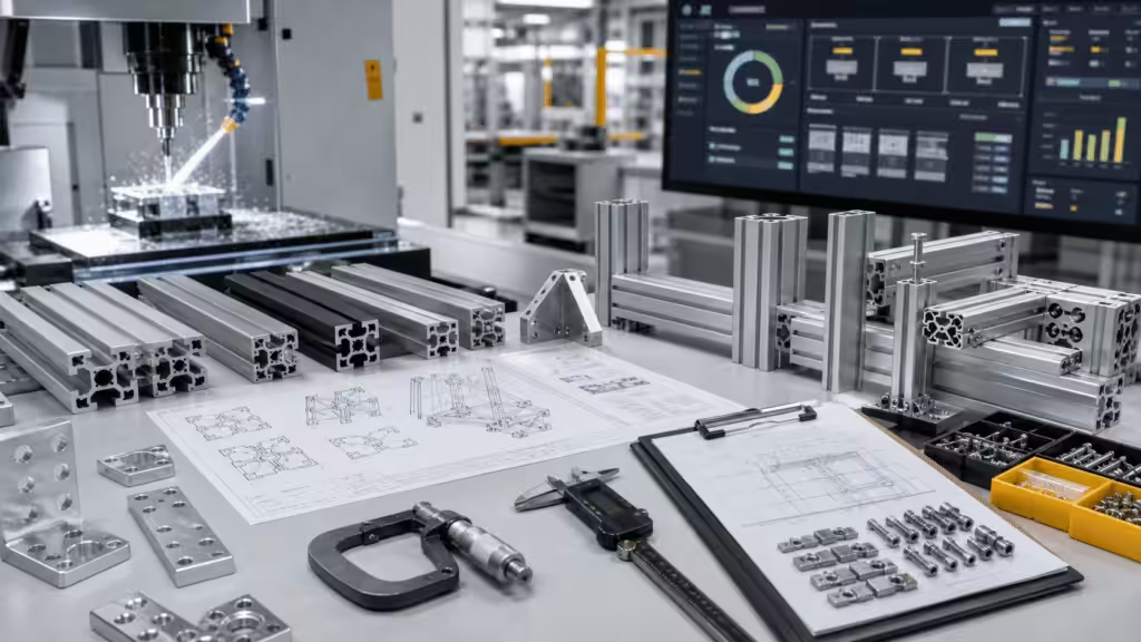
The first assembly tests the system, drawing, supplier, and work instructions at the same time. Build the highest-risk configuration before ordering full production quantities. A perfect single corner on a salesperson’s desk does not validate a long, loaded, vibrating frame.
Inspect Incoming Profiles and Hardware
Verify part number, alloy or material certificate where required, finish, quantity, cut length, end squareness, burrs, straightness, twist, slot condition, machining, threads, and packaging damage. Inspect representative nuts and brackets for dimensions, plating, thread quality, and correct engagement.
Label members so their identity survives cutting, machining, and assembly. Segregate nonconforming parts. Hand-fitting a wrong component into the prototype only teaches production to inherit the problem.
Check Squareness, Alignment, and Controlled Torque
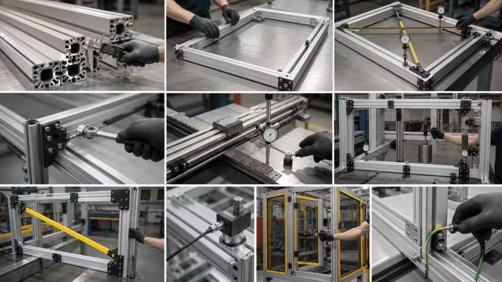
Assemble the base on a suitable flat reference. Start with joints loose enough to adjust. Measure diagonals, square the bays, set critical heights, then install braces and tighten in a defined sequence.
Use controlled tools for critical fasteners. Record the torque program, connector, bolt, and any thread preparation. Mark completed joints if visual inspection is part of the process.
Mount linear rails or precision plates only after the supporting structure meets its geometry requirements. Check alignment through the full travel or working envelope, not at one polite location near the center.
Test Deflection, Racking, Vibration, and Door Cycles
Test the performance limits defined at the start:
- Measure beam movement under representative point and distributed loads
- Apply lateral load to check racking and anchor behavior
- Run motors or moving equipment through expected speeds and accelerations
- Cycle doors, hinges, latches, interlocks, and removable panels
- Inspect joints for slip, witness-mark movement, or slot damage
- Verify grounding, ESD continuity, drainage, or sealing where required
Our internal laboratory documentation lists 58 sets of professional test equipment, 2,000 m2 of test space, and a 10-person test team. Its capabilities include mechanical tests, rapid temperature change, thermal shock, humidity, random vibration, impact, high-temperature aging, and salt spray.
Those resources were documented for thermal-product programs. They only become relevant to a T-slot assembly when the project has its own fixtures, loads, cycles, sensors, and acceptance criteria. A vibration chamber cannot validate an undefined requirement, although it can shake the ambiguity very enthusiastically.
Define Release Criteria and Change Control
Release production only when the drawing, BOM, cut list, machining files, hardware, torque instructions, assembly sequence, inspection plan, test report, and approved sample agree.
Our internal APQP workflow includes DFM, BOM review, DFMEA, PFMEA, control plans, measurement-system analysis, statistical process control, sample reports, PPAP, and lessons learned. A one-off T-slot frame may not need every automotive deliverable. The scalable principle is to connect each important risk to a control and a record.
Define who can approve deviations and how revisions reach purchasing, machining, assembly, and service teams. If the design changes a nut or bracket, recheck the interface and any affected load path.
12. Common T-Slot System Selection Mistakes
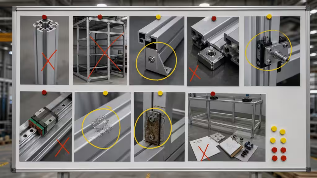
Most poor selections are not caused by obscure metallurgy. They come from skipping a plain question early in the project.
| Mistake | Why it causes trouble | Better action |
|---|---|---|
| Selecting by outer size | Same envelope can hide different walls and inertia | Approve the exact part-number datasheet |
| Asking for one weight capacity | Span, support, direction, and deflection are missing | Define the real load case and movement limit |
| Loading the weak axis | Rectangular profile stiffness is wasted | Orient the high-inertia axis toward the load |
| Treating joints as rigid | Corners can slip or rotate | Use tested connectors and validate the assembly |
| Leaving bays unbraced | Rectangles rack under lateral force | Add diagonals, gussets, or designed shear panels |
| Mixing brands by series name | Slots and nuts may not engage correctly | Measure samples and run a physical fit test |
| Choosing hardware after CAD | Panels or equipment block installation | Model hardware and tool access from the start |
| Using V-slot as a precision rail by default | Wheels may not meet load, wear, or accuracy needs | Evaluate the motion system separately |
| Ignoring finish and environment | Corrosion, ESD, or cleaning failures appear later | Specify exposure and verify the finished assembly |
| Comparing profile price only | Machining, connectors, labor, and downtime are hidden | Cost the finished frame and lifecycle |
| Skipping the first article | Production repeats drawing and process errors | Build, measure, test, and approve the risky bay |
The most expensive mistake is buying a system before deciding what evidence would make it acceptable. That reverses engineering: first the answer arrives, then everyone searches for a question it can survive.
13. Final T-Slot System Selection Checklist
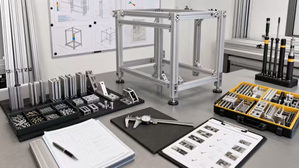
Use this checklist before approving a system or requesting a production quote.
Requirements and Load Cases
- Define the structure, motion, safety, and environmental functions.
- Record the positions and directions of static, dynamic, accidental, and maintenance loads.
- Set limits for deflection, alignment, racking, vibration, and door sag.
- Include anchors, panels, cables, service access, and future modifications.
Profile Sizing and Joints
- Base calculations on the exact profile part number and loaded axis.
- Check beams, columns, torsion, and local loads where relevant.
- Document the connector type, fastener, torque, and load direction.
- Define how each open bay will resist racking.
Compatibility and Supply
- Physically verify the slot geometry and critical accessories.
- Confirm that hardware remains installable and serviceable after fitting panels and equipment.
- Review CAD files, technical data, stock policy, and change-notification procedures.
- Include machining, assembly, inspection, freight, and spares in the finished-frame cost.
Production Release
- Put cutting, machining, finishing, and inspection requirements on controlled drawings.
- Measure a first assembly under representative conditions.
- Confirm that the BOM, work instructions, torque process, and test report match the approved sample.
- Define part, lot, revision, and nonconformance traceability.
If several checks remain unresolved, the project is not ready for a larger profile. It is ready for better information.
Frequently Asked Questions
What Is the Strongest T-Slot Aluminum Profile System?
There is no universally strongest T-slot system. Strength depends on the exact cross-section, alloy condition, profile orientation, unsupported span, load type, joints, bracing, and allowed deflection. Compare supplier data for the real configuration. For critical dynamic or safety-related structures, validate the complete assembly or involve a qualified engineer.
Is 30 mm or 40 mm T-Slot Better?
Neither size is automatically better. A 40 mm family often offers higher stiffness and larger connectors, while a 30 mm system may be lighter, smaller, and adequate for a braced guard or fixture. Compare the exact section properties, span, joint system, accessory needs, and available space.
How Much Weight Can T-Slot Aluminum Support?
T-slot aluminum has no single weight limit. Capacity changes with profile geometry, span, support condition, load position, bending axis, connection method, and acceptable movement. Use the manufacturer’s exact section data and the correct beam or column model, then test the assembled structure when joint behavior or dynamic loading matters.
Can Hardware from Different T-Slot Brands Be Mixed?
Sometimes, but never from the nominal series name alone. Measure the slot and mating hardware, check bracket tabs and thread engagement, and build a sample joint. Loaded or safety-related connections need a test in the real force direction. Treat unverified cross-brand compatibility as a design risk, not a purchasing convenience.
Is T-Slot Aluminum Suitable for CNC Machine Frames?
Yes, when the frame, joints, rail-mounting surfaces, and anchors meet the machine’s stiffness, alignment, and vibration limits. Use dedicated linear guides and controlled datums for precision axes. Heavy cutting loads, compact envelopes, or high damping requirements may favor welded steel, cast structures, or a hybrid design.
When Should a Custom Extrusion Replace a Standard System?
Consider a custom extrusion when repeated builds can remove several parts or reduce machining. It may also improve sealing, cable routing, or a datum along the full length. Keep a standard system when volume is low, changes are likely, or field replacement matters. Compare tooling, qualification, post-machining, and lifecycle savings with real volumes.
Choose the System You Can Verify
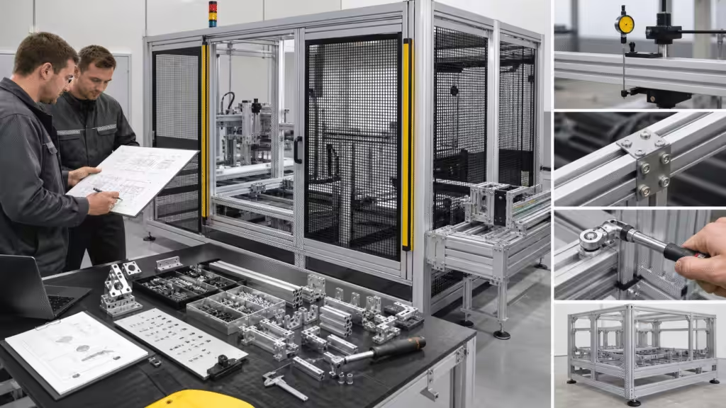
The best T-slot aluminum profile system is one your team can verify. Use requirements, calculations, interface checks, supplier records, and a measured first assembly. Brand familiarity can shorten the search. It cannot approve the design.
Start with the design basis and the highest-risk bay. Calculate it, build it, and measure it before committing the full BOM. For deeper guidance on beam checks, joints, bracing, compatibility, and production controls, read our Ultimate Guide to T-Slot Aluminum Profiles for Engineering.
Our documented manufacturing capabilities include standard and custom 6063 extrusions, custom anodizing, machining up to 1,600 mm, full-dimensional FAI, automated 5-axis production, and traceable inspection workflows. For a system review, provide the frame envelope, load cases, movement limits, expected volume, finish, critical interfaces, and target installation date. That gives engineering something more useful than “make it sturdy,” a requirement with admirable confidence and terrible units.