
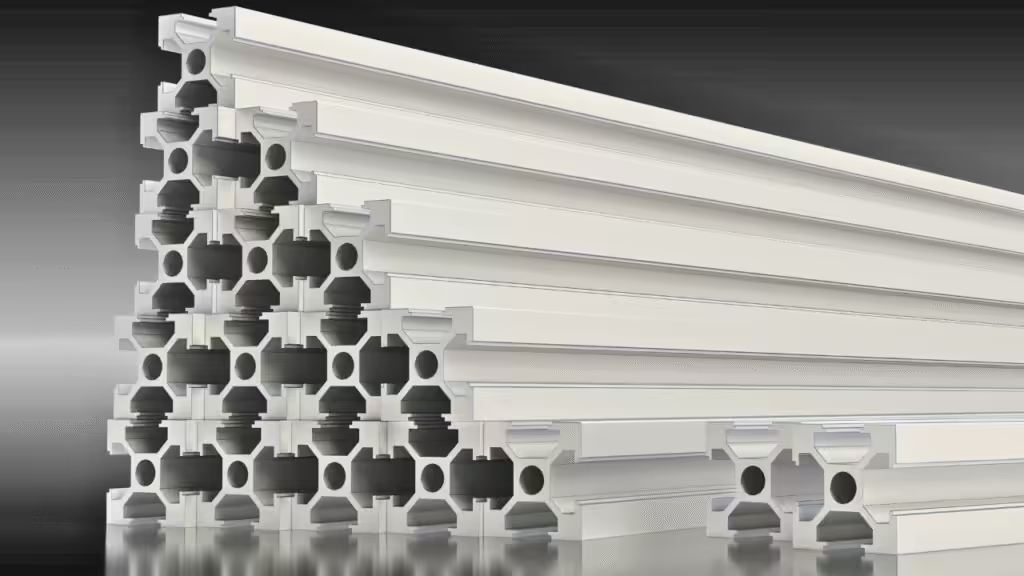
Aluminum channel extrusions look simple until two suppliers send you profiles with the same name and different corners, wall thicknesses, openings, and tolerances. One fits the panel. The other becomes a very straight, very expensive paperweight.
The right channel starts with function. Does it carry a beam load, hold a glass panel, guide a sliding part, hide wiring, move heat, or provide an adjustable mounting interface? That answer determines the useful cross-section long before alloy, finish, or color enters the meeting.
This guide compares 10 versatile aluminum channel extrusions for precision projects. For each type, you will see its best use, main design advantage, and most likely problem. We also cover alloys, extrusion tolerances, CNC finishing, first-article inspection, and custom tooling costs.
Quick Answer: Which Aluminum Channel Should You Choose?
Choose an aluminum channel by its load path and mating interface, not by the letter it resembles. Profile names are useful search terms. They are not inspection specifications.
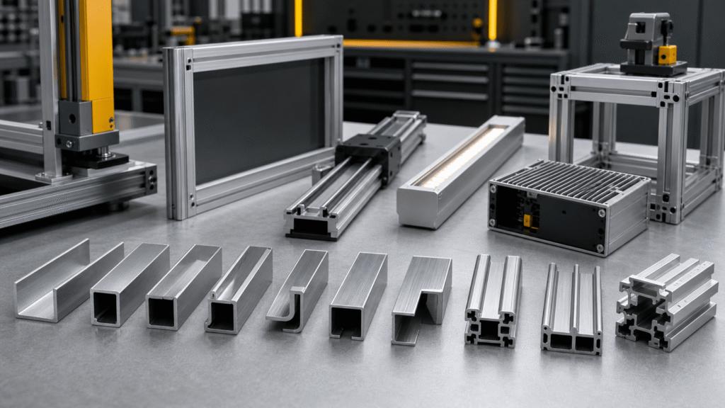
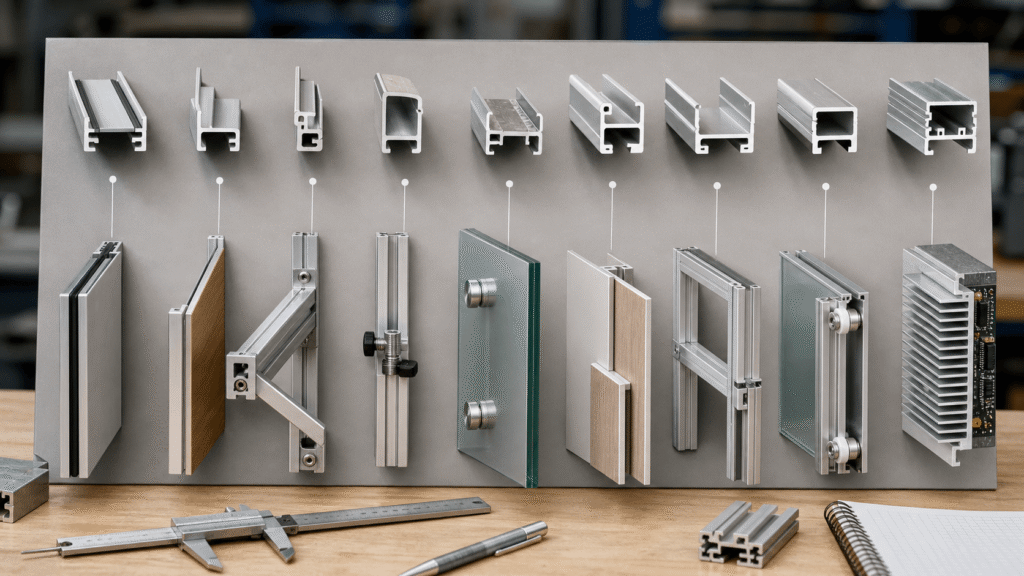
Use an equal-leg U-channel for simple retention and guides. Choose an architectural channel for visible trim, or a structural C-channel for beams and supports. Lipped C-channel accepts captive hardware. J-channel retains one edge. Hat channel creates a stand-off, while Z-channel connects offset planes. T-slot supports adjustable assemblies. H-channel guides two panels. A custom channel can combine several functions in one repeated part.
Before approval, define the load, span, supports, orientation, allowed movement, mating parts, environment, finish, annual volume, secondary work, and inspection method.
This method avoids a common trap. A thicker channel may carry more load. It may also close the opening, block a tool, or change the bend radius. Soon, a low-cost extrusion becomes a CNC project wearing an extrusion costume.
What Is an Aluminum Channel Extrusion?
Web, Flanges, Lips, Opening, and Inside Radius
An aluminum channel extrusion is a constant cross-section pushed through a die as a long profile. Its open side distinguishes it from a fully enclosed tube, but the useful details sit inside that broad definition.
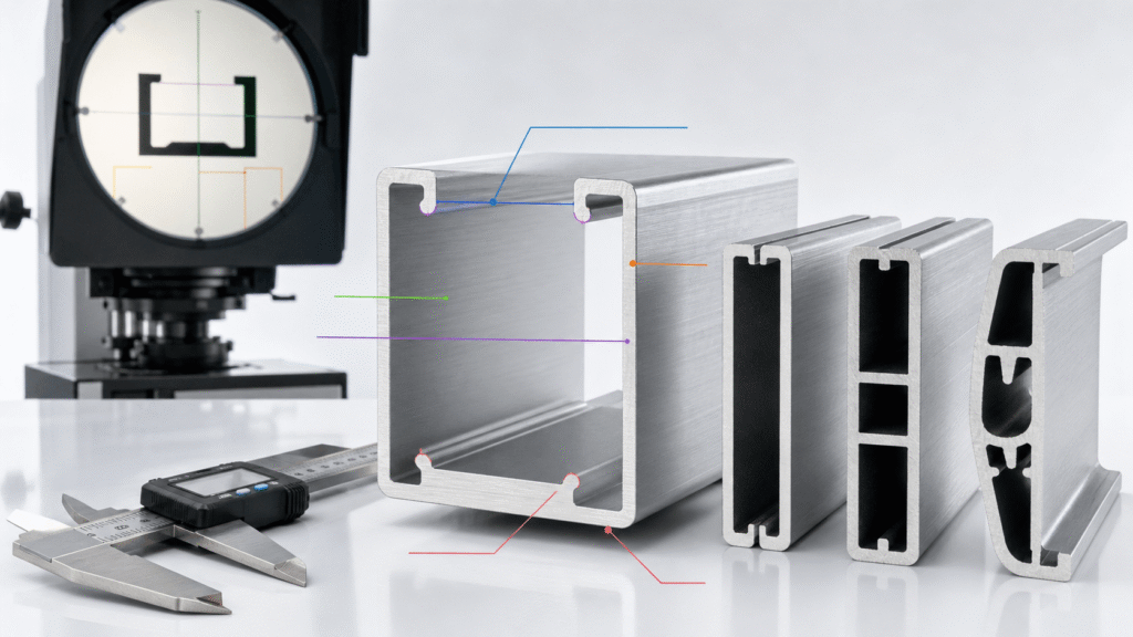
The web forms the base. The flanges, often called legs, extend from it. Some channels add lips for stiffness, retention, or hardware. The opening controls access and fit. The inside radius affects clearance, metal flow, and die strength.
These features set the bending axes. A deep web may be stiff in one direction and flexible in the other. Open sections can twist under offset loads. For structural work, request section area, centroid, moments of inertia, section moduli, and torsional data for the exact profile.
Solid, Semi-Hollow, and Function-Integrated Profiles
The Aluminum Extruders Council groups extrusion shapes as solid, hollow, or semi-hollow. A basic U-channel is often treated as a solid profile. A narrow opening around a large void may make a channel semi-hollow. That can change die design, tooling risk, tolerance, and cost.
A function-integrated channel may combine grooves, covers, screw bosses, cable paths, thermal surfaces, seals, or datums. This can remove parts and assembly steps. It can also create thin walls, deep tongues, and crowded tolerances, so every feature needs to pay rent.
Keep the cross-section constant where possible. Holes, threads, pockets, and notches need secondary work. Extrusion makes length efficiently. It does not drill a side hole halfway down the bar while nobody is looking.
Why Supplier Names Must Be Confirmed with a Drawing
Channel names are not universal dimensional standards. One supplier may call a basic three-sided profile a C-channel. Another uses that name for a heavier profile with radiused corners or lips.
Release a part from a controlled drawing, not a product nickname. At minimum, show:
- Overall width and height
- Web, flange, and lip thicknesses
- Clear opening and internal depth
- Inside and outside corner radii
- Critical datums and mating dimensions
- Cut length, end squareness, and burr limits
- Straightness, twist, flatness, and profile tolerances
- Alloy, temper, finish, visible surfaces, and packaging requirements
The Aluminum Association calls the opening between channel legs a space dimension when more than 25% is open space. Its extrusion tolerance guidance also separates straightness, twist, flatness, and metal-versus-space measurements. A panel fits the free opening, not the dimension the buyer hoped the supplier meant.
Top 10 Aluminum Channel Extrusions
1. Standard Equal-Leg U-Channel
The equal-leg U-channel has a flat web and two similar flanges. It suits panel edges, guards, trim, cable protection, tracks, guides, and light frames. It is also easy to orient, cut, drill, and inspect.
Its simplicity does not create a universal load rating. Beam behavior changes with orientation, and offset loads can cause twist. For sliding inserts, opening width, straightness, burrs, and finish buildup may matter more than ultimate strength. Use unequal legs when one side needs more reach or protection.
2. Architectural Sharp-Corner Channel
Architectural channel prioritizes clean lines, visible surfaces, and close-fitting interfaces. Typical uses include display frames, door and window details, cabinet trim, signage, reveals, and finished panel edges.
“Sharp corner” needs translation before it reaches the purchase order. Extrusions need radii and smooth transitions for metal flow and die life. A square seat may require relief, a mating chamfer, or machining. The AEC design guidance recommends avoiding knife edges. Mark exposed faces and define acceptable die lines, color, gloss, handling marks, and packaging.
3. Structural C-Channel
Structural C-channel uses a deeper or heavier cross-section for beams, rails, equipment supports, vehicle components, and industrial frames. The web carries shear while the flanges place material away from the neutral axis to resist bending.
Use the supplier’s exact section properties and support condition. Check stress, deflection, local bearing, tear-out, torsion, and column buckling as needed. Design the connections too. A rigid-looking channel can still rotate at a thin bracket, crush under a washer, or slip at a weak joint.
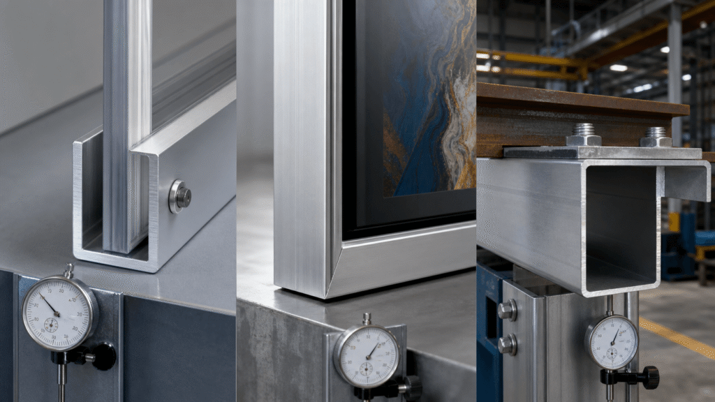
4. Lipped C-Channel or Strut Channel
A lipped C-channel turns the ends of the flanges inward. Those lips can stiffen the opening, retain a channel nut, locate a cover, or create a track for adjustable hardware. Extruded aluminum strut channels use this idea for equipment supports, service frames, solar hardware, and modular mounting.
The lip is also a local load feature. Verify its thickness, radius, opening, and engagement with the actual nut. A nut may contact only an edge, rotate, or pull through. Test the physical joint in each critical force direction and record the fastener and torque.
5. J-Channel and J-Cap
J-channel uses one long flange and one short flange. It is useful for panel starts, trim, sign edges, wall systems, door details, protective caps, and assemblies that need one open side for installation.
The unequal legs make access easy but create an asymmetric section. Loads on the long leg can twist the profile or pry at fasteners. Treat J-channel as an edge solution unless calculations support more. For visible work, define the exposed leg and end finish.
6. Hat Channel
Hat channel has a raised central web, two legs, and outward mounting flanges. It creates a stand-off while giving installers broad surfaces for screws, rivets, adhesive tape, or welds. Common uses include equipment skins, ceiling and wall systems, vehicle panels, enclosures, insulation gaps, and cable clearance.
Its shape can give good stiffness for low mass, but wide thin surfaces may bow. Control flatness only on functional faces. Also check tool access near the legs before placing holes.
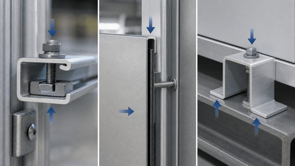
7. Z-Channel
Z-channel connects two parallel surfaces at different elevations. It appears in panel overlaps, equipment cladding, roof and wall systems, solar mounting, vehicle bodies, and assemblies that need a deliberate offset.
Opposing flanges allow access from separate sides, but the offset creates eccentric loading. Check twist, flange bending, pull-out, and local bearing. Long exterior runs may also need slotted holes or sliding details for thermal movement.
8. T-Slot or Slotted Modular Channel
T-slot profiles place one or more undercut slots along their faces. Captive nuts and connectors can move before tightening. This helps with automation frames, workstations, guards, fixtures, sensor mounts, and prototypes that will change after commissioning.
Treat the profile, T-nut, bracket, and fastener as one system. Measure the undercut, lips, slot depth, bracket tabs, and tool clearance. Test the real load direction. Our T-slot aluminum profile selection guide covers structural sizing, joints, and compatibility.
9. H-Channel or Double-Track Channel
An H-channel accepts panels or inserts from opposite sides. A double-track channel places two parallel paths in one profile. Suppliers do not always use these names consistently, so the drawing remains the adult in the room.
These profiles suit sliding doors, glass, cabinet panels, covers, and paired guides. Control slot width, center distance, depth, straightness, divider thickness, and finished clearance. Provide drainage, seals, end stops, and access for cleaning or replacement.
10. Custom Multifunction Aluminum Channel
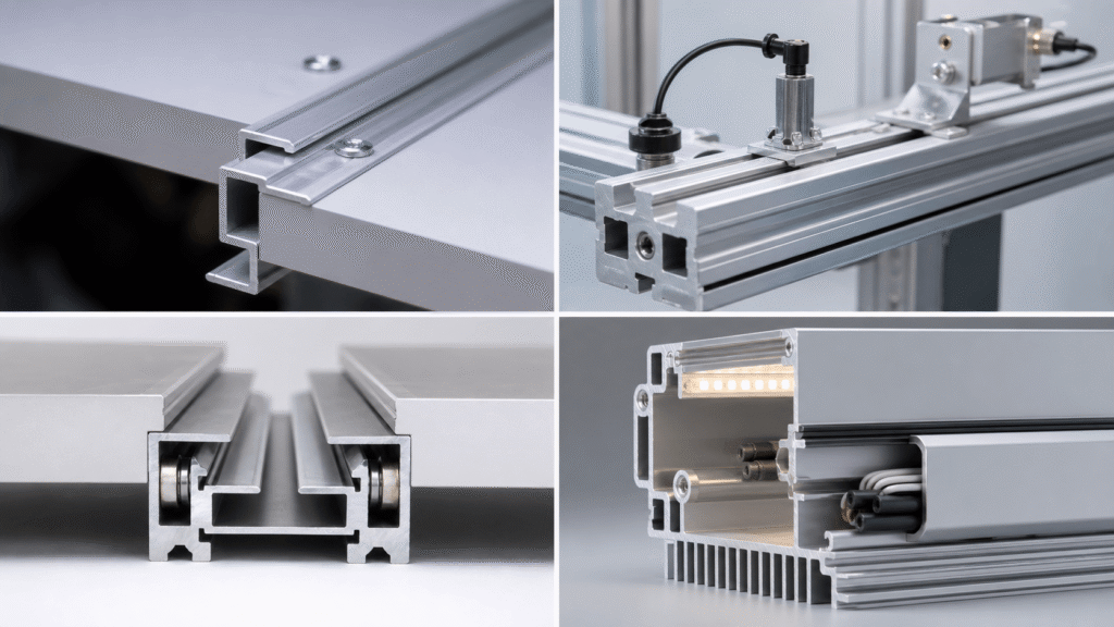
A custom channel combines the open profile with features built for one product. Examples include an LED-strip shelf, thermal fins, cable raceway, gasket groove, snap-fit lens, screw bosses, machined datum, panel slot, or decorative face.
This option works when integration removes enough parts, machining, alignment, or assembly time across repeated builds. Our LED aluminium profile installation guide shows how one channel can combine thermal and mechanical functions.
Keep the first die focused. Review wall balance, tongue depth, radii, finish access, datums, and inspection points. Prototype the mating parts early. An integrated feature saves time only when it still fits.
How to Select the Right Aluminum Channel
Define Loads, Span, Supports, and Allowed Deflection
Start with a free-body diagram. Record supports, load positions, and profile orientation. Include weight, acceleration, impact, vibration, fastener preload, and maintenance loads where relevant.
Set an allowed movement. A channel can remain below yield yet bind a door or misalign a sensor. For a simple center-loaded beam, deflection changes with the cube of span and inversely with E x I. Shortening the span or rotating the channel can beat adding wall thickness.
Use the exact section properties. Check both axes, torsion, local loads, columns, joints, and anchors as needed. Use a qualified engineer for safety or fatigue risks.
Choose the Alloy and Temper
Alloy and temper belong together. “6063 aluminum” is incomplete because O, T5, T52, and T6 conditions do not share the same mechanical properties.
Choose 6063 when extrudability, a high-quality surface, anodizing response, electrical or thermal performance, and architectural detail lead the decision. Hydro’s current 6063 alloy data sheet lists 6063-T6 extrusions at a minimum 0.2% yield strength of 170 MPa for the covered wall-thickness range. It lists typical thermal conductivity at 201 W/m-K.
Choose 6061 when medium-to-high structural strength matters more than the best cosmetic finish. Hydro’s 6061 alloy data sheet lists a 240 MPa minimum yield strength for 6061-T6/T6511 in the covered sizes. It gives typical thermal conductivity as 167 W/m-K.
These figures compare named conditions in one supplier’s data. Check wall thickness, temper, forming, welding, finish, and the governing specification before substitution.

Match the Finish to the Environment
Mill finish may suit hidden indoor parts. Anodizing can improve wear, corrosion behavior, surface insulation, and appearance. Powder coating offers more colors but can chip, bridge gaps, or alter fit.
Define the finish before freezing mating dimensions. Mark electrical contact areas, adhesive surfaces, sliding tracks, threads, tight bores, and cosmetic faces. Decide whether those regions receive finish, masking, or post-finish machining.
Approve color and texture on a representative sample. Alloy, temper, die condition, preparation, and batch conditions affect appearance. A signed limit sample beats a hopeful color name.
Check Heat, Grounding, and Dissimilar Metals
An aluminum channel can spread heat, but it is not automatically a heat sink. Check contact, wall thickness, exposed area, airflow, and nearby temperature limits.
For grounding or shielding, create deliberate contact points. Anodized surfaces resist current, so use masking, bonding hardware, or prepared surfaces. Verify continuity after finishing.
Both Hydro sheets warn that dissimilar metals can cause galvanic corrosion. Select compatible fasteners, isolate vulnerable joints, and provide drainage.
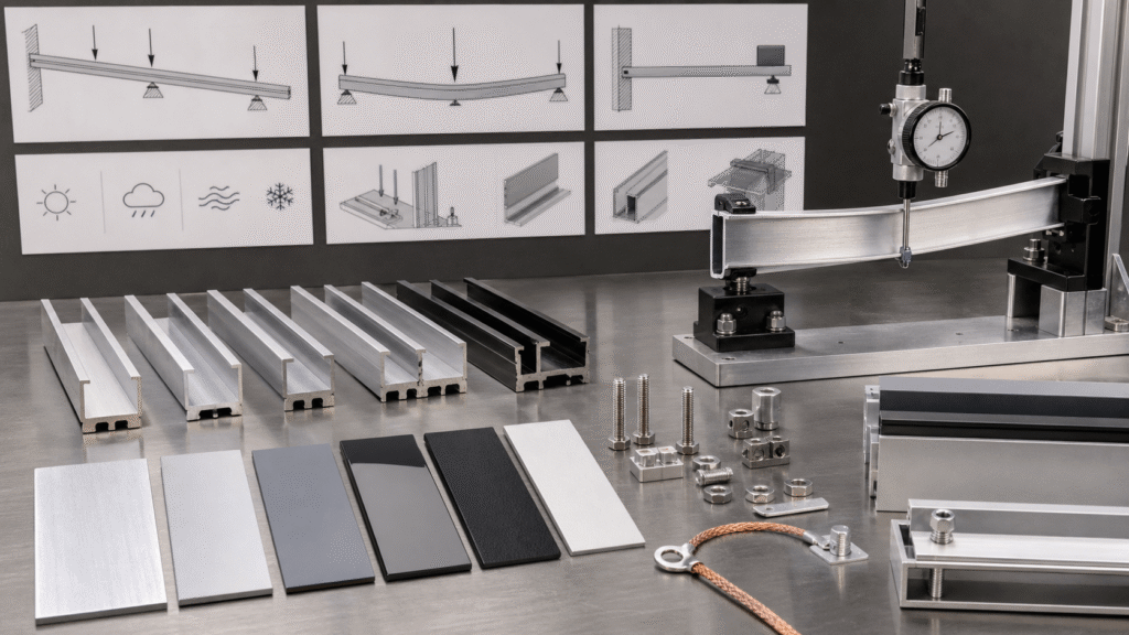
Design for Precision Before Cutting the Die
Specify Datums, Metal Dimensions, and Space Dimensions
Choose datums from surfaces that locate the real assembly. A mounting face may be primary. A side wall can control lateral position. An end can locate length if squareness and burrs are controlled.
Dimension mating interfaces from those datums. Avoid long chains across several walls and gaps. Separate metal dimensions, such as wall thickness, from openings and other space dimensions.
Apply geometric tolerances only where they protect function. Profile can control a cross-section, position can locate holes, and perpendicularity can control a cut end.
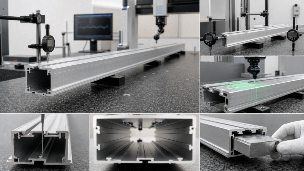
Control Straightness, Twist, Flatness, and Wall Variation
Long extrusions can bow and twist. Wide faces can lose flatness. Walls and openings vary within process capability. These errors interact. Clamping a bowed channel flat may move a slot. Forcing a twisted track into place may preload the sliding part.
The AEC tolerance overview points to Aluminum Standards & Data for standard and precision limits. Many extruders can hold tighter limits when needed, but tighter is not free.
State the measurement length, supports, orientation, temperature, and restraint. For tracks, inspect opening and straightness with a real mating part. One caliper reading does not certify three meters of travel.
Use Balanced Walls, Radii, Ribs, and Smooth Transitions
Balanced wall thickness helps metal flow through the die and cool more evenly. Symmetry reduces distortion risk. Generous radii and tapers protect die features and reduce abrupt thick-to-thin transitions.
The AEC recommends uniform walls, smooth transitions, symmetry, and useful ribs or grooves. These are guidelines, not a ban on complex shapes. An extruder can adjust the die when function demands awkward geometry.
Use ribs to add stiffness and index grooves to guide drilling or inspection. Avoid ornamental complexity on hidden faces. The press does not award points for plot twists.
Simulate the Risks That Matter
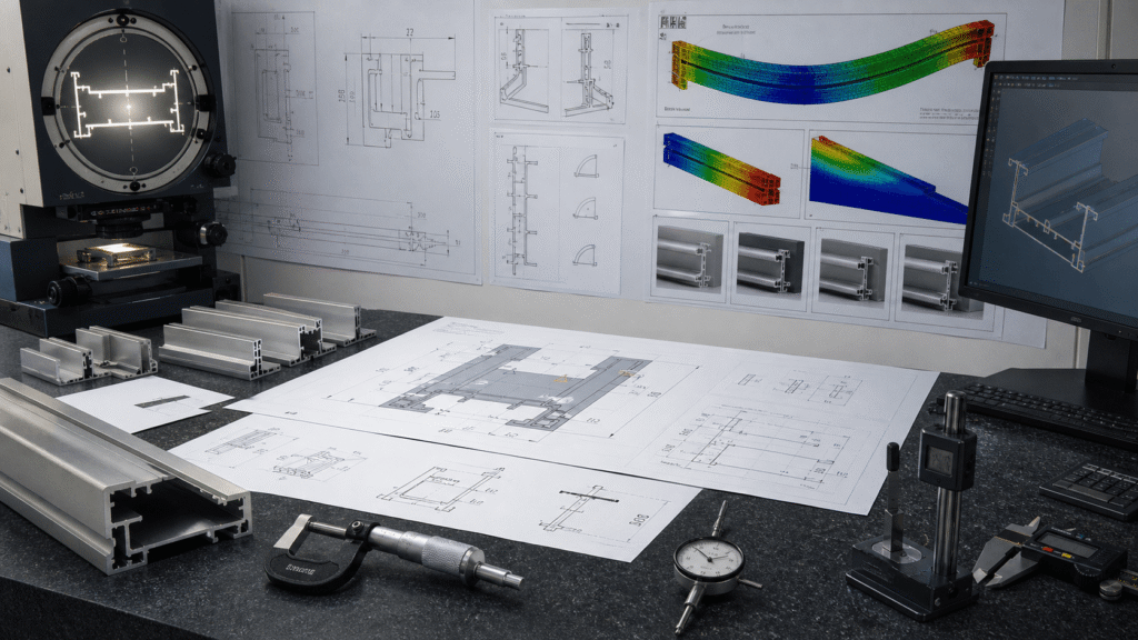
Use beam calculations first. Add finite-element analysis for local loads, cutouts, thin lips, torsion, or unusual supports. Use thermal or flow models only when the channel carries heat or fluid.
Our documented engineering workflow uses Ansys for mechanical analysis, Fluent for fluid analysis, and Flotherm for thermal work. In those adjacent thermal-product programs, optimized design shortened the recorded development cycle by 50%. That result is evidence for front-loading analysis, not a promise that every channel die arrives in half the time.
Simulation needs measured inputs and a test plan. State assumptions, contacts, constraints, material, mesh checks, and limits. Compare the model with prototype data. A colorful contour without a test is still mostly office decor.
Standard Channel or Custom Extrusion?
Use a Standard Profile for Low Volume and Fast Replacement
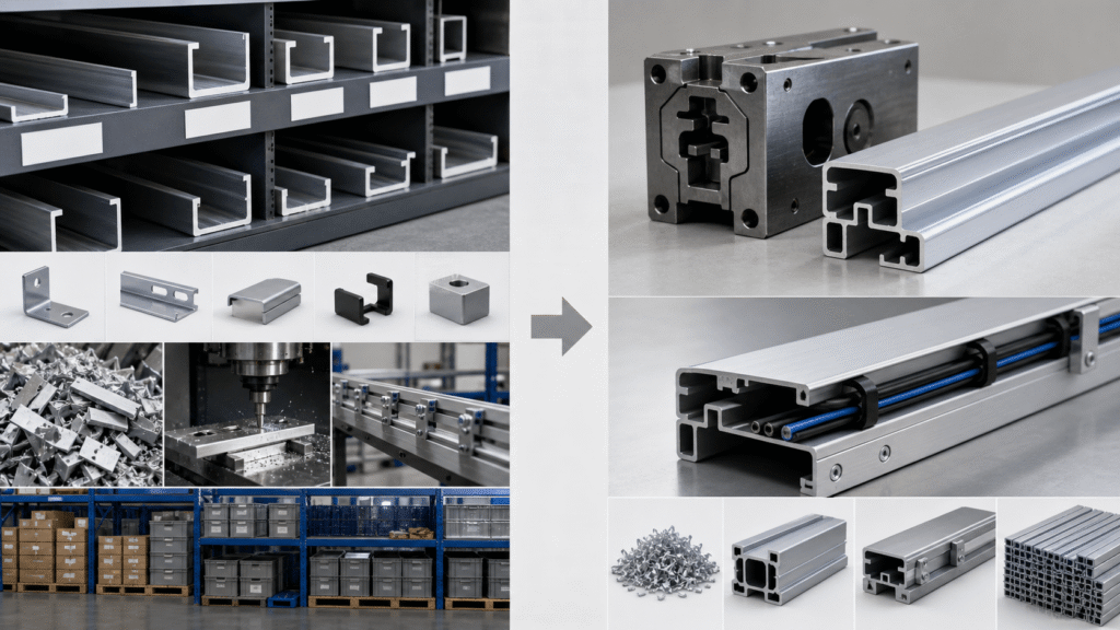
Standard channels avoid tooling and suit prototypes, repairs, and low-volume builds. Choose one when its properties, opening, finish, length, and tolerance meet the design. Verify the exact part number before freezing CAD. “One-inch U-channel” can hide several walls, radii, alloys, and openings.
Use a Custom Profile to Consolidate Parts and Interfaces
A custom extrusion earns its place when it removes recurring work. One channel may replace a bent bracket, cover, spacer, cable guide, heat spreader, and alignment rail. The AEC notes that integrating functionality can reduce secondary operations and speed assembly.
Our documented thermal-product range includes standard and custom 6063 extrusions plus custom anodize colors. That adjacent capability is useful when channel functions run along the full length. Features that appear only once may still belong in a CNC operation.
Start with the mating parts, load path, installation sequence, and inspection method. Confirm that the profile can be gripped, machined, finished, measured, and packaged.
Calculate Tooling, Annual Volume, Scrap, and Post-Machining
Compare finished-component cost, not price per meter. Count die and trial charges, minimum order quantity, material yield, cut loss, straightening, heat treatment, finish, and machining. Add inspection, packaging, freight, assembly labor, inventory, and future revisions.
One internal manufacturing guide describes extrusion as suitable for high-volume production with low non-recurring engineering cost. It also says the process is most cost-effective when post-machining is not required. That is relative process guidance, not a universal break-even volume.
Use real annual demand and a realistic revision horizon. Compare expected volume, low volume, and a design revision after first production.
Secondary Machining, Finishing, and Assembly
Cutting, Drilling, Tapping, CNC Machining, and Deburring
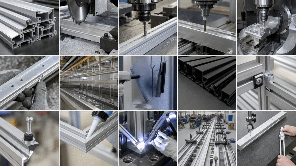
The AEC notes that extrusions rarely go straight from the press into use. Put each cut, hole, thread, and machined feature on a controlled drawing. Define datums, tool access, position, length, squareness, burrs, and protected surfaces. Thin walls may need support, while deep channels may need special tools or fixtures.
Our machining documentation lists a 1,600 mm maximum work size, tool-life control, several machine types, and full-dimensional FAI. The geometry, clamping, travel, and inspection method still need review.
Mill Finish, Anodizing, and Powder Coating
Choose the finish from the environment and the interface. The AEC finishing guide identifies mill surface, anodizing, paint, and mechanical treatments as common paths for extruded components.
Sequence matters. Cutting before anodizing can leave bare ends. Machining afterward exposes metal and may mark visible faces. Powder coating can fill grooves and threads unless masked.
Define finish class, masking, rack marks, color limits, gloss, tests, and packaging. Inspect fit after the complete finish.
Fasteners, Welding, Adhesives, and Thermal Expansion
Fasteners offer serviceability. Check edge distance, thread engagement, bearing area, locking, torque, and corrosion isolation.
Welding creates permanent joints but changes local properties in heat-treated alloys. Both Hydro data sheets warn that T6 strength can decrease in the weld region. Design the weld, filler, heat-affected zone, distortion control, cleaning, and post-weld acceptance as one process.
Adhesives spread load but need controlled preparation, bond line, cure, and environmental validation. Different finishes may need different processes.
Allow long members to expand. Fix one reference point, then use gaps, sliding joints, or slots to control movement.
Validate the First Article
Inspect the Exact Material, Dimensions, and Finish
The first article tests the drawing, die, process, machining, finish, packaging, and inspection plan. Approve it before production repeats the same error at scale.
Confirm the material certificate, temper, profile revision, die identity, and finish batch. Measure walls, openings, lips, radii, bosses, and grooves at several positions.
Under agreed lighting, inspect die lines, scratches, color, gloss, rack marks, cut ends, burrs, and packaging damage.
Measure the Critical Interfaces on the Finished Part
Measure finished interfaces: panel openings, track centers, machined holes, rail faces, and other features that control function.
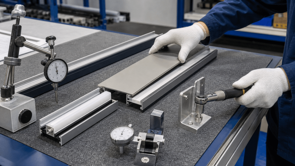
Use representative mating parts. Slide the real panel through the track. Install the real channel nut. Seat the gasket. Snap in the lens. Torque the real bracket. Functional gauges reveal edge contact, finish buildup, and tool-access problems early. A coordinate report may describe them only after everyone has learned several new words.
Define the gauge, supports, restraint, temperature, sample positions, and acceptance rule. Long profiles can change shape under their own weight.
Test Representative Loads and Environmental Risks
Build the highest-risk assembly and apply representative loads. Measure movement, pull-out, sliding force, seal compression, vibration, or temperature as needed.
Our internal laboratory documentation lists 58 sets of professional test equipment, 2,000 m2 of test space, and a 10-person test team. Available methods include mechanical testing, failure analysis, rapid temperature change, thermal shock, humidity, random vibration, high-temperature aging, and salt spray.
Select tests from real failure modes. Dry indoor trim does not need an automotive vibration campaign. A coastal enclosure may need corrosion, sealing, bonding, and thermal checks.
Release Production with Traceable Records
Release production only when all controlled records agree. Check the drawing, CAD model, material, die revision, finish, machining program, inspection plan, approved sample, and purchase order.
Our APQP workflow uses DFM, BOM review, DFMEA, PFMEA, control plans, MSA, SPC, dimensional reports, PPAP, and lessons learned. A stock U-channel needs less paperwork. A critical custom channel still needs each risk tied to a control and record.
Internal records also describe barcode traceability, automatic flatness inspection, and MES tracking. Confirm which controls apply. Define segregation, deviation approval, and revision control before release.

Common Aluminum Channel Selection Mistakes
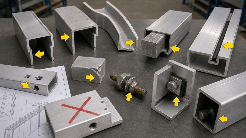
Most aluminum channel failures start as an omitted requirement. Avoid these common mistakes:
- Buying by profile name: U, C, J, and architectural channel names vary. Approve a dimensioned drawing and exact part number.
- Ignoring the loaded axis: Open profiles can be stiff in one direction and flexible or torsion-prone in another. Model the installed orientation.
- Asking for one load capacity: Capacity depends on alloy, temper, cross-section, span, supports, load position, direction, joints, and allowed movement.
- Specifying impossible sharp corners: Match mating parts to realistic extrusion radii or add deliberate relief and machining.
- Over-tolerancing the whole profile: Tighten only dimensions that protect fit, motion, sealing, appearance, or load transfer.
- Dimensioning from unstable surfaces: Use functional datums and avoid long tolerance chains across several walls and gaps.
- Freezing the finish late: Anodizing, paint, masking, and post-finish machining affect clearance, conductivity, appearance, and cost.
- Adding secondary operations casually: Every hole, notch, tapped feature, and special cut needs tool access, fixturing, inspection, and cycle time.
- Treating a joint as rigid: Check fastener engagement, local bearing, slip, rotation, corrosion isolation, and service access.
- Ignoring thermal movement: Long channels need a controlled fixed point and room to expand.
- Skipping mating-part trials: A caliper cannot reproduce every interaction between finish, radii, seals, panels, nuts, and assembly tools.
- Ordering production before FAI: Approve the complete finished first article and its records before multiplying the risk.
The expensive mistake is not choosing the wrong alphabet letter. It is approving a shape before deciding what evidence would make it acceptable.
Frequently Asked Questions
Is U-Channel Stronger Than C-Channel?
Not from the name alone. Strength and stiffness depend on the exact cross-section, alloy, temper, orientation, span, supports, load position, and connections. Some suppliers use U-channel and C-channel for similar shapes. Compare dimensioned profiles and section properties for the real loaded axis.
Is 6061 or 6063 Better for Aluminum Channels?
6061 is often the better starting point for higher structural strength. 6063 is often preferred for extrudability, detailed profiles, visible surfaces, anodizing response, and thermal or electrical applications. Temper matters as much as alloy. Verify the exact material data, wall range, forming, welding, finish, and availability before selecting either.
How Much Weight Can an Aluminum Channel Hold?
There is no single weight rating for aluminum channel. Calculate the actual beam, column, local-load, torsion, and connection conditions. Set an allowed deflection as well as a strength limit. For critical applications, test the finished assembly because joints, holes, cutouts, and mounting surfaces affect performance.
Can Aluminum Channels Be Bent After Extrusion?
Yes, but bendability depends on alloy, temper, wall distribution, bend axis, radius, equipment, and cosmetic requirements. Tight bends in a hard T6 condition can crack or distort. Hydro’s 6061 guidance notes that severe bends may require softer T1, T4, or O conditions followed by suitable heat treatment. Qualify the bend process on the actual profile.
What Tolerances Should a Precision Channel Specify?
Specify only the limits required for function. Common controls include opening width, wall thickness, profile, straightness, twist, flatness, cut length, end squareness, hole position, and finished-interface dimensions. Define datums and measurement methods, then align the requirements with Aluminum Association standards and the extruder’s demonstrated capability.
When Is a Custom Aluminum Channel Worth the Tooling Cost?
A custom channel is worth evaluating when repeated volume lets the profile remove purchased parts, machining, fastening, alignment, scrap, or assembly time. Compare finished cost across expected, low-volume, and revision scenarios. Keep a standard profile when demand is small, changes are likely, or field replacement is more valuable than integration.

Choose the Cross-Section You Can Verify
Start with the job, not the catalog. Define the load path, interfaces, allowed movement, environment, annual volume, and inspection evidence. Then choose the simplest standard or custom aluminum channel extrusion that meets those requirements.
For a supplier review, send the cross-section drawing, cut length, material, finish, critical datums, mating parts, and load cases. Add volume, secondary operations, cosmetic surfaces, packaging, and the target date. That package gives engineering something measurable. “Make it precise” is motivational, but it has yet to appear on a calibrated gauge.
Our source package documents standard and custom 6063 extrusion programs for thermal products, custom anodize colors, and design analysis. It also documents CNC and 5-axis machining, a stated 1,600 mm machining envelope, tool-life control, full-dimensional FAI, environmental testing, and production traceability. The correct process depends on the quoted geometry and risk. We verify that fit during DFM instead of treating adjacent capability as a channel-specific result.
For adjacent design decisions, read our Ultimate Guide to T-Slot Aluminum Profiles for Engineering and Aluminum Heatsinks: Types, Function, and Efficiency Explained.