

Aluminum heatsinks move heat away from electronic components by spreading heat through a metal base and releasing it into air through fins, pins, or other extended surfaces. They are popular because aluminum is light, easy to extrude or machine, cost-effective, and thermally good enough for a very large share of electronics cooling problems.
That last phrase matters: “good enough” is not faint praise. In thermal design, good enough means the chip survives, the fan does not scream like a tiny vacuum cleaner, and the purchasing team does not start looking at copper quotes with haunted eyes.
This guide explains the main aluminum heatsink types, how they work, what makes them efficient, and how to choose one without treating datasheets like fortune cookies.
We will also use real production and catalogue data from internal company materials: AL6063 BGA heatsinks, forced-air thermal resistance tables, 300W and 350W GPU air-cooling modules, 160 W/mK high-conductivity die-cast aluminum material, 58 sets of test equipment, 2,000 square meters of lab space, and real manufacturing constraints such as CNC machining, die casting, skiving, brazing, heat pipes, vapor chambers, and liquid cooling.

What Is an Aluminum Heatsink?
An aluminum heatsink is a passive or fan-assisted thermal component that transfers heat from a hot device into the surrounding air. It usually includes a flat base for contact with the component and fins or pins that increase surface area.
The general heat sink definition is simple: a heat sink transfers heat from a device to a fluid medium, usually air or liquid coolant. In electronics, the device may be a CPU, GPU, BGA chip, LED, power module, converter, motor driver, or telecom board.
Aluminum is common because it hits a practical middle:
- It conducts heat well enough for many electronics.
- It is much lighter than copper.
- It can be extruded into complex fin shapes.
- It can be machined, die cast, forged, stamped, skived, and anodized.
- It usually costs less than copper.
Pure copper conducts heat better. Nobody is arguing with the periodic table. But copper is heavier, more expensive, and harder to use in some high-volume shapes. Aluminum wins many real programs because the final design is not judged by conductivity alone. It is judged by thermal performance, mass, cost, process, assembly, lead time, and whether the board still fits in the box.
How Aluminum Heatsinks Work
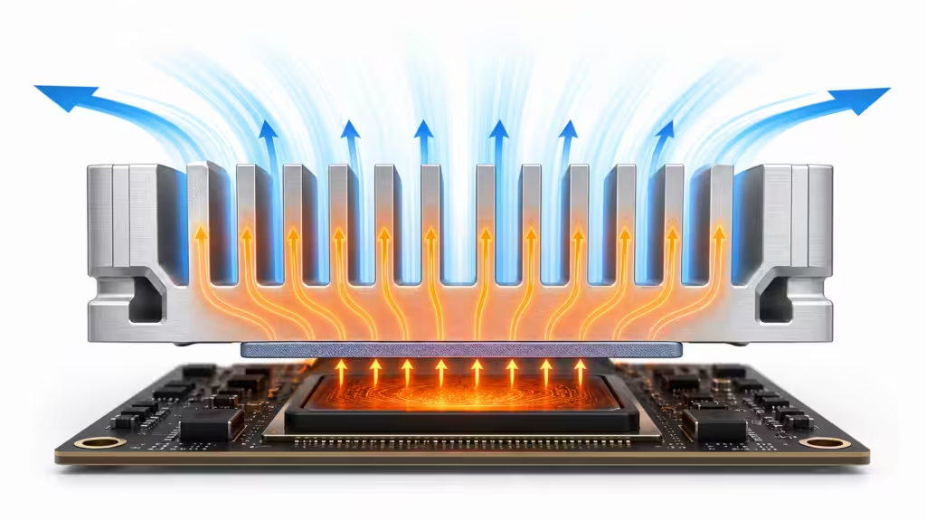
Aluminum heatsinks work through three heat-transfer steps:
- Conduction moves heat from the chip or package into the heatsink base.
- Spreading moves heat through the base into fins, pins, or a heat pipe zone.
- Convection moves heat from the metal surface into air. Radiation can help, but convection usually does the heavy lifting in electronics cooling.
The thermal path looks like this:
Junction -> case -> thermal interface material -> heatsink base -> fins -> air
Each layer adds thermal resistance. Thermal resistance is usually shown in C/W. A heatsink rated at 2 C/W will rise about 2 C above ambient for each watt it dissipates under the stated test condition. That last phrase matters. Test condition is where many thermal dreams go to get a haircut.
Airflow changes everything. In the internal catalogue data for BGA heatsinks, many parts list Theta_SA values at 200, 400, and 600 LFM. One AL6063 round pin heatsink for a 37.5 mm BGA package shows thermal resistance dropping from 3.4 C/W at 200 LFM to 1.9 C/W at 600 LFM for one 11.6 mm height variant. Same metal, same family, different airflow. The heatsink did not become smarter. The air finally showed up to work.
Main Types of Aluminum Heatsinks
There is no universal best aluminum heatsink. There are only better fits for a heat load, airflow path, package size, height limit, cost target, and manufacturing method.
Extruded Aluminum Heatsinks
Extruded aluminum heatsinks are made by pushing heated aluminum alloy through a die to form long fin profiles. The profile is then cut to length and often machined, drilled, tapped, anodized, or fitted with clips.
They are the everyday workhorse of aluminum cooling.
Use extruded heatsinks when you need:
- Good cost efficiency
- Repeatable production
- Straight fins or plate fins
- Custom lengths from the same profile
- Standard shapes for BGA, DC-DC converters, LEDs, and power electronics
Internal catalogue data lists AL6063 as a common alloy for extruded heatsinks and repeatedly notes it is used for optimum heat transfer. That matches common industry practice. AL6063 is popular because it extrudes cleanly and delivers a good balance of thermal performance, surface finish, and manufacturability.
The limitation is geometry. Extrusion works best when the fin shape can be pulled through a die. Very thin, very tall, or highly complex fins may push the process outside its happy place. And when manufacturing gets unhappy, cost tends to bring a chair and stay awhile.

Skived Aluminum Heatsinks
Skived heatsinks are made by shaving thin fins directly from a metal base. Because the fins and base are one continuous piece, the thermal path can be excellent.
Skiving is useful when you need:
- Thin fins
- High fin density
- Strong base-to-fin conduction
- Custom performance in a compact area
- No separate bonded fin interface
The company catalogue notes thin-fin skiving with fins as thin as 0.008 inch for copper, with aluminum also available. That is the point of skiving: it can create geometry that normal extrusion may not handle as cleanly.
Skiving is not always the cheapest route. But for dense cooling where fin efficiency and base contact matter, it earns its keep.

Stamped Fin Heatsinks
Stamped fin heatsinks use sheet metal fins formed by stamping. They are often combined with heat pipes or vapor chambers when the design needs a larger fin area without a fully machined block.
Use stamped fins when:
- Weight matters
- Fin area must be large
- Airflow is available
- Heat pipes or vapor chambers spread heat into the fin pack
- Production volume supports tooling
Stamped fins are common in compact high-performance modules because they let designers separate two jobs: spreading heat and rejecting heat. A heat pipe or vapor chamber spreads energy. The stamped fin stack dumps it into air. Elegant, if the soldering and assembly behave.
Forged Aluminum Heatsinks
Forged heatsinks use pressure to form aluminum into pin or fin geometries. Forging can create high aspect-ratio features and good mechanical strength.
Internal catalogue materials note forged heatsinks with extremely high aspect ratios up to 35:1, available in copper and aluminum. That ratio matters because taller, thinner pins or fins can improve surface area in limited footprints, especially where airflow comes from multiple directions.
Forged heatsinks are useful for:
- Pin fin arrays
- BGA cooling
- Omni-directional airflow
- Dense electronic modules
- Designs where machining every fin would be silly expensive
Forging is not magic. It still needs draft, tooling, tolerances, and post-processing. But when pin geometry and production repeatability matter, it can be a strong option.
Die-Cast Aluminum Heatsinks
Die-cast aluminum heatsinks are formed by injecting molten aluminum alloy into a mold. Casting can create complex shapes, mounting bosses, housings, and integrated thermal structures.
The internal catalogue mentions die casting in special aluminum alloy with thermal conductivity of 160 W/mK and high aspect-ratio pin fins up to 10:1. A separate automotive domain-controller project used a brazable die-cast material with thermal conductivity up to 160 W/mK around a local SoC cooling design.
Die casting is useful when a heatsink is also a structural housing.
Use it for:
- ECU housings
- LED housings
- Automotive controllers
- Telecom enclosures
- Integrated mounting features
- Complex pin-fin or enclosure shapes
The trade-off is that not all die-cast aluminum alloys conduct heat equally well. Thermal conductivity, porosity, wall thickness, and process control matter. A die-cast heatsink with trapped porosity is not a heatsink. It is a very confident piece of thermal confetti.

Round Pin and Cross-Cut Aluminum Heatsinks
Round pin heatsinks work well when airflow direction is not fixed. Straight fin heatsinks prefer airflow along the fin channels. Pin fins are more forgiving when air comes from different angles.
This matters for BGA packages, compact boards, and enclosures where airflow can swirl, bypass, or enter from multiple directions.
In one internal selector table, aluminum round pin BGA heatsinks are described as suitable for omni-directional airflow. For a 37.5 mm series, aluminum round pin variants show thermal resistance values as low as 1.4 C/W at 200 LFM and 0.8 C/W at 600 LFM for a 24.6 mm height option. That is a useful reminder: geometry, height, and airflow can move the result a lot.
Fansinks
A fansink is a heatsink with a fan attached. It uses forced airflow to reduce thermal resistance.
Fansinks are useful when:
- Natural convection is not enough
- Board height allows a fan
- Acoustic limits are acceptable
- Dust management is handled
- Reliability targets allow moving parts
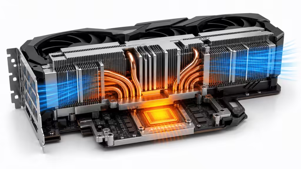
Company catalogue data for active BGA fansinks lists examples around 1.3 to 3.5 C/W depending on package size, fan voltage, height, and configuration. In a GPU air-cooling project, a 300W module used AL1100 fins at 0.3 mm thickness and seven heat pipes. Another 350W module used AL1100 fins at 0.3 mm thickness and six heat pipes in a loop-bending layout.
At that power level, the “heatsink” is no longer just a block of aluminum. It is a heat-moving ecosystem with fins, heat pipes, airflow, contact pressure, and mechanical support. Tiny weather system included.

Aluminum Heatsink Efficiency: What Actually Moves the Needle
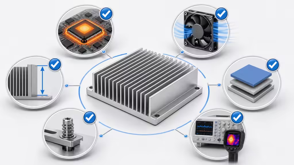
Heatsink efficiency depends on the whole thermal path, not just the metal. The key levers are thermal resistance, surface area, airflow, fin geometry, base spreading, TIM performance, mounting pressure, and environmental conditions.
Thermal Resistance
Thermal resistance tells you how many degrees Celsius the heatsink rises per watt of heat. Lower is better.
But thermal resistance is conditional. A value measured at 600 LFM does not apply to a sealed box with lazy airflow. If your product lives inside a dusty enclosure with a tired fan, do not borrow the hero number from a clean wind tunnel and call it engineering.
Surface Area and Fin Geometry
More surface area can improve heat rejection, but only if air can reach it. Fins that are too close together may restrict airflow. Tall fins can help, but fin efficiency drops when heat cannot travel effectively to the fin tips.
The practical design question is:
Can air pass through the fin field, and are the fins hot enough to be useful?
If the outer fins are cool while the base is cooking, the heatsink has a spreading problem.
Airflow
Airflow can transform performance. Internal selector tables repeatedly show thermal resistance improving as airflow rises from 200 to 600 LFM.
For example, a 40 mm round pin copper variant in the catalogue drops from 2.4 C/W at 200 LFM to 1.3 C/W at 600 LFM for one 11.6 mm height option. Aluminum variants show the same pattern, even if the absolute values differ.
This is why fan curves, duct design, bypass leakage, inlet temperature, and enclosure vents matter. A heatsink without airflow is like a spreadsheet without formulas: technically present, spiritually disappointing.

Thermal Interface Material
Thermal interface material, or TIM, fills microscopic gaps between the chip and heatsink. Air is a poor conductor, so gaps increase resistance.
Internal materials show several TIM-related capabilities:
| TIM or material type | Extracted project data | Practical meaning |
|---|---|---|
| Thermal pad | Conductivity >= 18 W/mK, thickness 1-7 mm, Shore 00 around 50 | Good for larger gaps and controlled compression |
| Thermal gel | Conductivity >= 16 W/mK | Useful for uneven gaps and dispensing |
| Thermal grease | Conductivity around 7 W/mK | Useful for thin bond lines and high contact performance |
| High-conductivity composite | Conductivity >= 50 W/mK in one material deck | Useful for special spreading paths or high-load modules |
TIM selection is not a beauty contest for W/mK. Bond line thickness, pressure, pump-out, surface flatness, rework, and aging all matter.

Surface Finish and Anodizing
Black anodizing is common on aluminum heatsinks. It can improve corrosion resistance and surface emissivity. In many forced-air electronics applications, convection still dominates, so anodizing is not a miracle button. It is useful, but it should not be asked to do the fan’s job.
Aluminum vs Copper Heatsinks
Copper conducts heat better than aluminum, but aluminum often wins when weight, cost, extrusion, machining, and system-level design matter.
| Factor | Aluminum heatsink | Copper heatsink |
|---|---|---|
| Thermal conductivity | Lower than copper, but strong enough for many applications | Higher, useful for spreading and compact hot spots |
| Weight | Light | Heavy |
| Cost | Usually lower | Usually higher |
| Manufacturability | Excellent for extrusion, casting, machining, forging | Strong for skiving, base plates, inserts |
| Best use | General electronics, BGA, LED, telecom, automotive housings | High heat flux, compact bases, premium cooling, copper inserts |
Company catalogue data shows the trade-off clearly. For several round pin BGA families, copper versions improve thermal resistance but weigh much more. In one 37.5 mm family, aluminum variants weigh around 16.1 to 23.3 g, while copper variants in the same family range from 55 to 80 g. That is not a rounding error. That is a board-level mechanical conversation.
The practical answer is often hybrid: aluminum fins or housing plus copper base, copper insert, heat pipe, or vapor chamber. Let copper handle the hot spot. Let aluminum handle area, weight, and manufacturability.

How to Choose the Right Aluminum Heatsink
Choose an aluminum heatsink by starting with the heat load, maximum allowed component temperature, ambient temperature, airflow, space limit, mounting method, and production process.
Here is a practical selection path.
- Calculate allowable thermal resistance
Use the temperature limit, ambient temperature, and heat load. If a chip can rise only 50 C above ambient and dissipates 25W, the total thermal path must stay under 2 C/W. That includes more than the heatsink. - Check airflow reality
Do you have natural convection, 200 LFM, 600 LFM, a tiny fan, or a sealed plastic box pretending to be a wind tunnel? - Pick the geometry
Straight fins fit directional airflow. Round pins fit uncertain airflow. Skived fins fit dense high-performance designs. Die-cast shapes fit structural housings. - Check height and keep-out zones
PCIe and BGA products often have brutal height limits. One catalogue note for PCIe fansinks mentions a PCIe card height restriction of 14.48 mm, leaving limited fin height once chip height is considered. - Select attachment and TIM
Clips, push pins, screws, adhesive tape, phase-change pads, and grease all change both thermal and mechanical behavior. - Prototype and test
Simulation is useful. Test data is where the polite lies stop.

Manufacturing Methods and When to Use Them
Manufacturing method is not just a supplier detail. It shapes thermal performance, lead time, tooling cost, geometry, and quality risk.
| Method | Best fit | Watch-out |
|---|---|---|
| Extrusion | Standard fins, good cost, scalable lengths | Limited by die geometry and aspect ratio |
| Skiving | Thin dense fins, strong base-to-fin path | Cost and process constraints |
| Stamping | Lightweight fin stacks, fan modules, heat pipe assemblies | Needs joining quality and tooling |
| Forging | Pin fins, high aspect ratios, BGA cooling | Tooling and design rules |
| Die casting | Complex housings, automotive modules, integrated bosses | Alloy conductivity and porosity control |
| CNC machining | Prototypes, low to medium volume, precision features | Unit cost and cycle time |
| Heat pipe or vapor chamber integration | High heat flux or spreading limits | Assembly, reliability, orientation, cost |
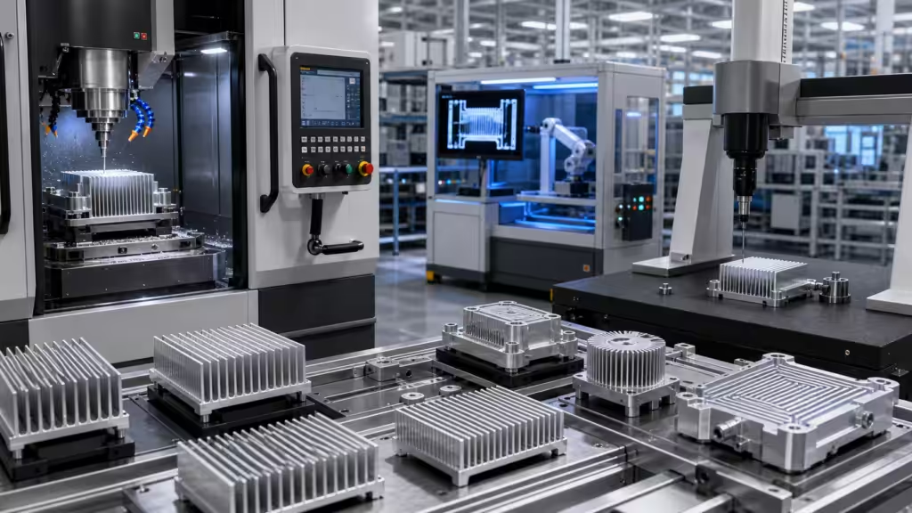
Internal company materials list processes including extrusion, skiving, casting, forging, CNC machining, heat pipes, vapor chambers, liquid cooling, die casting, aluminum brazing, laser welding, friction stir welding, and vacuum welding. Another capability deck lists a 1000T max die-casting machine, material analysis by spectrometer, X-ray process confirmation, and CMM dimensional confirmation.
That is the hidden part of heatsink buying. You are not just buying fins. You are buying process control.
Real Project Data: What the Numbers Teach
The most useful EEAT evidence is not “we are experienced.” It is real numbers tied to real design decisions.
BGA Heatsink Selector Data
The internal heatsink catalogue includes selector tables by BGA size. These tables list material, height, weight, and thermal resistance at 200, 400, and 600 LFM.
Examples:
| Product family | Material | Height | Weight | Thermal resistance pattern |
|---|---|---|---|---|
| 37.5004 round pin BGA | AL6063 | 11.6-24.6 mm | 16.1-23.3 g | 3.4 to 0.8 C/W across height and airflow cases |
| 37.5004 round pin BGA | CU1100 | 11.6-24.6 mm | 55-80 g | 2.9 to 0.7 C/W across height and airflow cases |
| Active BGA fansinks | Aluminum | around 17.4-25.2 mm | 33-45 g | around 3.5 to 1.3 C/W depending on model |
The lesson is not “copper always wins.” The lesson is that height, airflow, mass, and material all trade places. If your board cannot carry the mass, the copper result may be thermally cute and mechanically rude.
GPU Air-Cooling Modules
For a 300W GPU air-cooling module, the project data lists a 323.97 x 122.3 x 24.11 mm module using AL1100 fins at 0.3 mm thickness and seven heat pipes: two 8 mm pipes and five 6 mm pipes.
For a 350W GPU air-cooling module, the data lists about 325.9 x 120 x 25.7 mm, AL1100 fins at 0.3 mm thickness, and six loop-bent heat pipes: two 8 mm pipes and four 6 mm pipes.
That is where the word “heatsink” starts stretching. At 300W to 350W, air cooling usually needs a full assembly: fin stack, heat pipes, base flatness, fan curve, airflow impedance, vibration design, and mounting pressure.
Automotive Domain Controller Data
In an 8295-class domain controller air-cooling project, one production-oriented design used an AlSi10Mn(Mg) die-cast thermal base, copper block, aluminum fins, and a 60W single heat pipe with reflow integration.
In an 8775-class air-cooled domain control module, thermal simulation showed Tj = 114.90 C under the project boundary conditions.
These examples show why aluminum heatsinks often become hybrid thermal systems. The aluminum structure provides area and manufacturability. Copper or heat pipes handle hot spots. TIM and mounting pressure decide whether the whole stack behaves or merely poses for the CAD screenshot.
Testing: Where Heatsink Efficiency Becomes Real
A heatsink is not efficient because the model says so. It is efficient when the tested part meets temperature, airflow, pressure drop, vibration, assembly, and reliability requirements.
Internal lab capability data includes:
- 58 sets of professional test equipment
- 2,000 square meters of test area
- 10-person professional test team
- Flow resistance and thermal resistance testing
- Sealing performance testing
- Mechanical performance testing
- Pressure resistance testing
- Product failure analysis
- Welding performance analysis
- Cleanliness analysis
- Rapid temperature change
- Thermal shock
- Alternating damp heat
- Random vibration
- High-temperature aging
- Composite salt spray
- Fan performance testing
For aluminum heatsinks, the most important tests are often thermal resistance, airflow, fan curve, contact pressure, vibration, and dimensional inspection.
If a supplier cannot explain the test condition behind a C/W number, treat the number like a suspiciously perfect benchmark. It may still be useful. It just needs adult supervision.

Common Aluminum Heatsink Mistakes
Mistake 1: Choosing by Size Alone
A bigger heatsink often helps, but only if heat can spread into it and air can move through it. A large block with poor contact can lose to a smaller design with better TIM, pressure, and airflow.
Mistake 2: Copying a Datasheet Number Without Airflow
Thermal resistance depends on airflow. If the number was measured at 600 LFM and your product has natural convection, do not copy it into the design review unless you enjoy awkward silence.
Mistake 3: Ignoring Mounting Pressure
TIM works when it is compressed correctly. Too little pressure leaves air gaps. Too much pressure bends the board or damages the package.
Mistake 4: Picking Copper When Aluminum Plus Design Would Work
Copper can improve spreading, but it adds mass and cost. Sometimes an aluminum heatsink with better airflow, a heat pipe, or a vapor chamber is the better system answer.
Mistake 5: Treating Surface Finish as Magic
Anodizing is useful. It is not a tiny black cape that lets the heatsink fly.
Aluminum Heatsink Applications
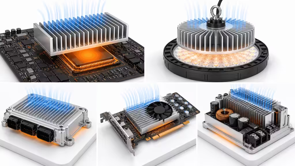
Aluminum heatsinks appear anywhere electronics need stable temperatures without excessive weight or cost.
Common applications include:
- BGA chipsets
- CPUs and GPUs
- PCIe cards
- DC-DC converters
- LED lighting
- Power supplies
- Telecom and networking equipment
- Automotive ECUs and domain controllers
- Industrial control modules
- Consumer electronics
- Drones and compact embedded systems
- Energy storage and EV thermal modules
Internal company materials also show cross-industry coverage: automotive and transportation, data centers, industrial equipment, aerospace, consumer electronics, and military applications. The product matrix includes integrated modules, liquid cooling, machined parts, welded assemblies, heat pipes, vapor chambers, TEC, copper, aluminum, and stainless steel.
That breadth matters because real heatsink projects rarely stay in one neat box. A product may start as “just an aluminum heatsink” and become a heat pipe assembly, then a vapor chamber, then a liquid cold plate if power density keeps climbing. Thermal design has a way of escalating politely until someone brings a pump.
How to Improve Aluminum Heatsink Efficiency
To improve aluminum heatsink efficiency, work through the full heat path.
- Improve base flatness and contact area.
- Use the right TIM and bond line thickness.
- Increase airflow or reduce bypass leakage.
- Match fin orientation to airflow direction.
- Use pin fins for uncertain or omni-directional airflow.
- Increase fin area only when air can still pass through.
- Add a copper insert for local hot spots.
- Add heat pipes or vapor chambers when spreading limits the design.
- Use forced air when natural convection cannot meet the temperature target.
- Validate with thermal testing, not just simulation.
The most expensive fix is the one you discover after tooling. Run simulation early. Build prototypes. Measure thermal resistance. Then update the model. Repeat until the hardware stops arguing.
Aluminum Heatsink Selection Checklist
Use this checklist before choosing a heatsink:
- What is the heat load in watts?
- What is the maximum junction or case temperature?
- What is the ambient temperature?
- Is airflow natural or forced?
- What airflow rate is realistic?
- What is the maximum height?
- What is the package size?
- Is airflow directional or omni-directional?
- What mounting method is allowed?
- What TIM can the assembly process support?
- Does the design need shock and vibration resistance?
- Is the heatsink also a housing?
- Is weight a hard limit?
- Is copper needed only at the hot spot?
- Can the supplier test thermal resistance under your conditions?
If you can answer those questions, the heatsink choice becomes much calmer. Still not easy. But calmer.
Frequently Asked Questions
What is an aluminum heatsink used for?
An aluminum heatsink is used to move heat away from electronic components such as CPUs, GPUs, BGA chips, LEDs, power supplies, converters, and automotive ECUs. It spreads heat into fins or pins, then releases that heat into air through convection.
Are aluminum heatsinks better than copper heatsinks?
Aluminum heatsinks are usually better for weight, cost, extrusion, and many high-volume designs. Copper heatsinks conduct heat better and help with compact hot spots, but they are heavier and more expensive. Many high-performance designs use aluminum plus copper inserts, heat pipes, or vapor chambers.
What aluminum alloy is used for heatsinks?
AL6063 is commonly used for extruded aluminum heatsinks because it balances thermal performance, extrusion quality, surface finish, and manufacturability. Internal catalogue materials repeatedly list AL6063 for BGA, fan, and plate-fin heatsink products.
What makes a heatsink efficient?
An efficient heatsink has low thermal resistance under the real operating condition. Efficiency depends on material, base spreading, fin geometry, surface area, airflow, TIM, mounting pressure, and ambient temperature. The test condition matters as much as the number.
Do black aluminum heatsinks cool better?
Black anodizing can help radiation and corrosion resistance, but in many electronics applications convection dominates. A black finish does not fix poor airflow, bad TIM, weak mounting pressure, or insufficient surface area.
When should I use a fan with an aluminum heatsink?
Use a fan when natural convection cannot keep the component below its temperature limit. Fans can reduce thermal resistance by increasing airflow, but they add noise, dust sensitivity, power draw, and reliability considerations.
Final Takeaway
Aluminum heatsinks are popular because they solve real thermal problems without making the product heavy, expensive, or impossible to manufacture.
The best design is not always the biggest block of metal. It is the design that matches the heat load, airflow, package size, mounting method, production process, and reliability target.
If you remember one thing, remember this: a heatsink is a system. Aluminum is the material. Efficiency comes from the whole chain.
And if someone hands you a thermal resistance number with no airflow condition, smile politely and ask for the test setup. That little question has saved more projects than many heroic late-night meetings.