
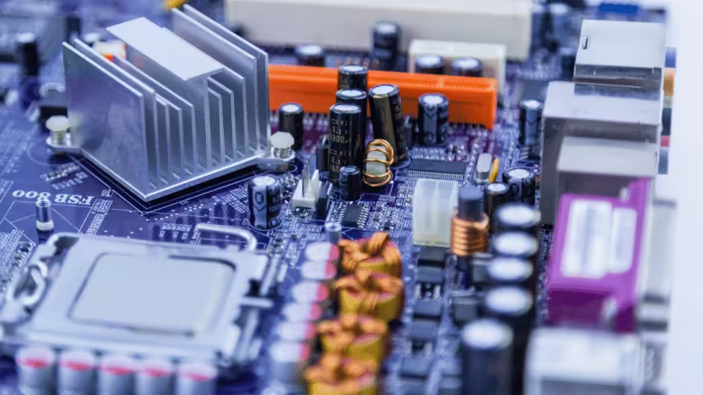
Extruded aluminum heat sinks are precision cooling parts made by pushing heated aluminum through a die, cutting the profile to length, and finishing it with machining, anodizing, mounting hardware, or thermal interface material. They are common in electronics because they give engineers a useful mix of heat transfer, low weight, repeatable geometry, and sane production cost.
That mix matters. A heat sink does not win because it looks like a tiny metal skyline. It wins because the chip stays inside its junction limit, the airflow path behaves, the mounting pressure is repeatable, and nobody discovers during pilot build that the “simple clip” needs three extra millimeters of keep-out area.
This guide ranks 10 extruded aluminum heat sink design families for precision cooling. It is not a random product parade. It is a practical selector for engineers, sourcing teams, and product owners who need to choose between low-profile BGA heat sinks, plate fin profiles, active fansinks, PCIe coolers, DC/DC converter heat sinks, wide extrusions, LED profiles, enclosure heat sinks, and hybrid extrusion assemblies.
We will also bring in real first-party engineering data from local company materials: AL6063 BGA heat sink tables, 200/400/600 LFM thermal resistance data, 0.3 mm and 0.4 mm BGA clearance requirements, 2.0 mm to 4.5 mm clip keep-out constraints, 58 sets of test equipment, a 2,000 square meter lab, 50 percent design-cycle reduction from Ansys, Fluent, and Flotherm workflows, and high-power cold plate projects that explain when an extrusion stops being enough.
Tiny spoiler: airflow is not a decorative variable. It is the main character wearing safety glasses.

Quick answer: which extruded aluminum heat sink should you choose?
Choose a low-profile plate fin extrusion for BGA chips with linear airflow. Choose a wider AL6063 plate fin extrusion when the heat load is higher and board space allows it. Choose an active fansink when airflow is weak or the chip is too hot for passive cooling. Choose a DC/DC converter extrusion when the package follows quarter-brick, half-brick, or full-brick layouts.
For rough screening, start with four numbers:
- Total heat load in watts.
- Maximum allowed component case or junction temperature.
- Ambient temperature near the heat sink, not the room temperature printed on the test plan.
- Available airflow in LFM or CFM through the actual fin channels.
Then calculate the required thermal resistance:
Required heat sink C/W = (Tmax - Tambient) / watts - upstream thermal resistance
That upstream part includes junction-to-case, case-to-TIM, TIM thickness, contact pressure, flatness, and mounting repeatability. If you ignore it, the math will still look beautiful. The hardware will simply disagree later, which is rude but traditional.
The general heat sink concept is simple: move heat from a hot device to air or liquid. The extrusion process is also simple in principle: force material through a die to create a constant cross section. The engineering work sits between those two simple ideas.
The top 10 extruded aluminum heat sinks for precision cooling
1. Low-profile AL6063 plate fin BGA heat sinks
Low-profile plate fin BGA heat sinks are the best first choice when the board has linear airflow, tight height limits, and a surface-mount package that needs a clean thermal path.
In the company catalogue, the INL Series is described as a low-profile aluminum plate fin BGA heat sink built from extruded AL6063. It uses optional EZ-Snap mounting clips, black anodize, and preassembled clip plus thermal pad options. The notes matter: some variants require only 0.3 mm chip clearance above the board, but the clip needs keep-out space around the package.
That is the kind of detail many generic heat sink guides skip. A heat sink can match the thermal target and still fail the layout if the keep-out area collides with nearby capacitors.
Use low-profile BGA plate fin heat sinks for:
- Embedded processors
- FPGAs with modest to medium power
- Network chips
- Compact industrial control boards
- Board designs where airflow has a clear direction
One 37.5 mm AL6063 plate fin example in the internal selector table lists a 12.7 mm height, 23.4 g weight, and Theta_SA values of 2.0 C/W at 200 LFM, 1.3 C/W at 400 LFM, and 1.1 C/W at 600 LFM. That airflow curve is the lesson. The same aluminum part becomes much more useful when the air path is real.
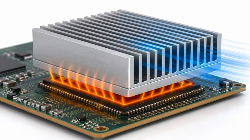
2. High-efficiency plate fin extrusions for mainstream electronics
High-efficiency plate fin extrusions are the everyday workhorse for precision cooling. They are not flashy. That is part of the charm. They give designers repeatable fin spacing, predictable airflow behavior, and a manufacturing route that scales without turning every part into a custom sculpture.
The HS1800, INL, and INH style families in the company catalogue all point to the same design logic: extruded AL6063, plate fin geometry, black anodize, optional clips or thermal tape, and compatibility with BGA or other surface-mount packages.
For a 42.5 mm BGA size, one HS1810EB plate fin example lists 12.7 mm height, 25.5 g weight, and thermal resistance of 2.2 C/W at 200 LFM, 1.3 C/W at 400 LFM, and 0.9 C/W at 600 LFM. A 45 mm plate fin family goes lower in taller variants, with one 32.6 mm high option listed at 0.9 C/W at 200 LFM, 0.7 C/W at 400 LFM, and 0.5 C/W at 600 LFM.
Use this family when you need:
- A predictable cost-performance balance
- Linear airflow from a fan, blower, or enclosure vent
- Good manufacturability
- Repeatable assembly with clips, push pins, or tape
- Multiple height options from the same design family
The trade-off is orientation. Straight plate fins prefer airflow along the channels. If air arrives from random directions, a round pin or cross-cut design may behave better. Aluminum does not negotiate with turbulence. It just gives you the bill in degrees C.
3. Narrow extruded aluminum heat sinks for dense PCB layouts
Narrow extruded aluminum heat sinks fit where the board designer has already spent every square millimeter like rent in downtown Silicon Valley.
The competitor article separates narrow, medium, and wide profiles by width. That is a good lens, but it should not be treated as a magic classification. Width is only one part of the thermal story. Height, base thickness, fin pitch, airflow direction, mounting method, TIM, and component power all change the outcome.
Narrow extrusions work best for:
- Small ICs near taller components
- Memory, RAM, and peripheral chips
- Edge-of-board cooling zones
- Low to moderate heat loads
- Multi-component layouts where one large heat sink will not fit
Internal small round pin data is not an extrusion example, but it gives a useful warning about small volume cooling. A 12.7 mm high miniature aluminum heat sink can move from 18.0 C/W at 100 LFM to 5.6 C/W at 600 LFM in one listed case. Small heat sinks are brutally sensitive to airflow. If airflow is weak, the tiny heat sink may be mostly decorative jewelry for a suffering chip.
For narrow extruded profiles, check the watts per inch of available width before you fall in love with the CAD model. If the number looks aggressive, widen the sink, add airflow, increase height, improve the TIM stack, or move the heat source. “Make the fins thinner” is not a universal cheat code.

4. Medium-width extruded profiles for balanced precision cooling
Medium-width extruded profiles are often the most practical choice for industrial electronics, power boards, motor controls, communication modules, and compact computing systems.
They have enough base area to spread heat, enough fin area to reject heat, and enough mechanical room for mounting features. They also tend to avoid the two classic extremes: the narrow sink that cannot carry the heat load, and the huge extrusion that cools well but blocks connectors, service access, or airflow to everything else.
Use medium-width extruded heat sinks when:
- The board has 2 to 6 inches of usable width.
- Airflow is available but not server-grade.
- The heat source is one larger package or several moderate packages.
- You need cut-to-length flexibility.
- The enclosure needs repeatable assembly and serviceability.
In first-party project materials, the engineering workflow uses mechanical Ansys, fluid Fluent, and thermal Flotherm simulation to shorten the design cycle by 50 percent. That matters most in this middle zone. Medium profiles often have enough design freedom that simulation can save multiple prototype loops.
The practical move is to simulate the profile, then test it on a board-level fixture. The same materials list 58 sets of professional test equipment, a 2,000 square meter testing area, and a 10-person test team covering thermal resistance, flow resistance, thermal shock, humidity, vibration, pressure, salt spray, high-temperature aging, and cleanliness.
That is not brochure confetti. Precision cooling needs measurement. Otherwise the heat sink is just a confident guess with fins.
5. Wide extruded heat sinks for high heat loads
Wide extruded aluminum heat sinks are useful when the heat load is too high for compact profiles and the system has enough width to spread heat before it reaches the fins.
Use wide profiles for:
- Power electronics
- Industrial drives
- Large LED engines
- Multiple components under one thermal rail
- Baseplate-mounted electronics
- Enclosures where the heat sink doubles as a structure
The advantage is surface area and spreading. The risk is airflow distribution. Wide fins can develop low-flow zones if the fan, duct, or vent layout does not feed the full width. A wide heat sink with lazy airflow in the center is like buying a gym membership and only walking to the vending machine.
For wide profiles, ask these questions before committing:
- Will air move across the entire fin field?
- Does the base need more thickness to reduce spreading resistance?
- Will one fan create a dead zone?
- Can the extrusion be cut, drilled, tapped, and anodized within tolerance?
- Is the assembly still serviceable?
If the heat source is highly concentrated, a plain extrusion may need help from a copper insert, vapor chamber, heat pipe, or liquid cold plate. That does not mean the extrusion failed. It means the heat flux moved beyond what a single aluminum path can handle efficiently.
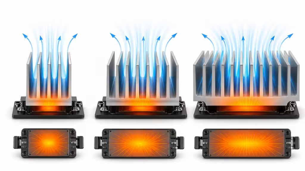
6. Active extruded aluminum BGA fansinks
Active BGA fansinks combine an extruded aluminum heat sink with a small DC fan. They are the right choice when passive convection cannot reach the target thermal resistance within the available footprint.
The company catalogue lists F-Series and FI/FJ active BGA heat sinks made from extruded AL6063 with DC fans, EZ-Snap clips, thermal interface material, and black anodize. Several fan-equipped BGA families list compact heights around 20 to 23 mm and C/W ratings around 1.2 to 3.5 depending on package size and fan configuration.
Use active extruded fansinks for:
- Hot BGA processors
- Communication ASICs
- Compact compute modules
- PCIe and accelerator cards
- Systems with limited passive airflow
The hidden cost is reliability. A fan adds acoustic noise, dust risk, bearing life, control logic, and field failure modes. It can be the right answer, but it is not free thermal magic. It is a tiny machine bolted to your thermal problem.
Good active fansink design checks:
- Fan voltage and speed range
- Acoustic target
- Dust path and service access
- Air recirculation inside the enclosure
- Clip pressure and TIM compression
- Vibration behavior
- Failure mode if the fan stalls
If the system cannot tolerate fan failure, the passive heat sink must still buy enough time for throttling or shutdown. The thermal design should fail gracefully, not dramatically.
7. PCIe extruded or skived fansinks for expansion cards
PCIe cooling is precision cooling with a ruler standing over your shoulder. The card height limit is tight, the chip may already be several millimeters tall, and the airflow often depends on a chassis plan you do not fully control.
The internal catalogue notes that PCIe cards have a height restriction of 14.48 mm. That limits available fin height, especially when a typical BGA chip height is around 3 mm including solder balls. The listed PCIe fansinks use 5 V or 12 V fans, thermal pads, and compact sizes such as 50 x 65 mm or 50 x 50 mm. One WV05L or WV12L style example lists a 50 x 65 mm footprint, 11 mm heat sink height, and 1.1 C/W rating.
Use PCIe fansinks for:
- Network interface cards
- Accelerator cards
- Edge AI cards
- Compact GPU or FPGA boards
- High-speed storage controllers
The design choice is often extrusion versus skiving. Extrusion is usually strong for cost and repeatability. Skiving can create thinner fins when geometry demands it. The company catalogue notes thin-fin copper skiving down to 0.008 inch, with aluminum also available. For a PCIe card, that can matter when every millimeter of fin height is already spoken for.

8. Push-pin extruded heat sinks for serviceable board assemblies
Push-pin extruded heat sinks are useful when assembly speed, field service, and repeatable contact pressure matter more than the absolute lowest part count.
The push-pin aluminum heat sink family in the internal catalogue uses AL6063 plate fin designs for linear airflow. Listed examples include widths and lengths around 1.45 x 2.28 inches, 2.28 x 1.45 inches, and 2.40 x 2.28 inches, with heights from 0.23 to 0.90 inches. Thermal resistance can drop sharply with height and airflow. One 1.45 x 2.28 inch longitudinal plate fin example moves from 4.1 C/W at 200 LFM for a 0.23 inch height to 1.2 C/W at 200 LFM for a 0.90 inch height.
That is a clean engineering reminder: taller fins can help, but only if the enclosure has space and the air path can use them.
Push-pin designs are strong when:
- The board can accept holes.
- The product may need rework.
- Contact pressure must be more repeatable than adhesive tape alone.
- Vibration and thermal cycling matter.
- Assembly operators need a fast, visible retention method.
Do not treat push pins as an afterthought. Spring force, PCB thickness, hole size, back-side clearance, and TIM compression all affect real thermal performance.
9. Extruded aluminum heat sinks for DC/DC converters
DC/DC converter heat sinks are a special category because the package shapes are common enough to justify repeatable heat sink families. Quarter-brick, half-brick, and full-brick converters often need plate fin or round pin heat sinks with hardware kits and thermal pads.
The company catalogue lists DC/DC converter aluminum heat sinks using AL6063 or 356.0 aluminum, with plate fin and round pin options. For quarter-brick examples, a longitudinal plate fin heat sink can move from 4.1 C/W at 200 LFM for a short 0.23 inch profile to 1.2 C/W at 200 LFM for a 0.90 inch profile. Full-brick examples go lower, with some listed values around 0.7 C/W at 200 LFM and 0.3 C/W at 600 LFM in taller configurations.
Use this design family when:
- The converter follows a standard brick format.
- You need repeatable hardware mounting.
- The airflow direction is known.
- The thermal pad can cover a flat baseplate.
- Reliability matters more than cosmetic minimalism.
One warning: converter heat does not always spread evenly across the baseplate. Check the module’s power map and contact area. A big extrusion mounted on a small hot zone can still suffer spreading resistance.
The practical question is not “Can this sink dissipate X watts?” The better question is “Can this exact converter, with this pad, pressure, airflow, and ambient temperature, stay inside its limit?” Less glamorous. Much more useful.

10. Hybrid extruded aluminum heat sinks with heat pipes or vapor chambers
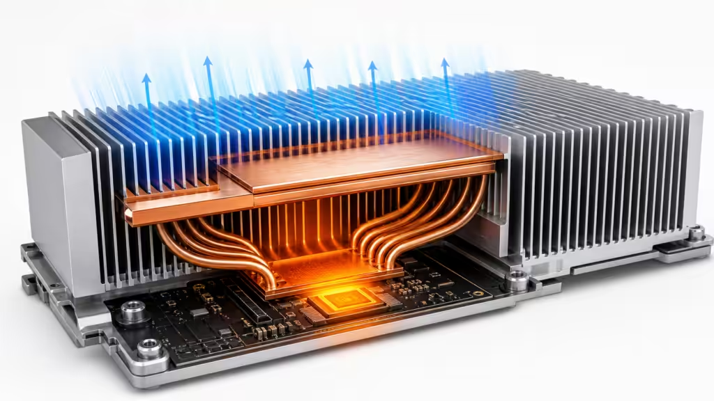
Hybrid extruded aluminum heat sinks are the bridge between simple air cooling and heavier thermal systems. They use an extrusion for fin area and structure, then add heat pipes, vapor chambers, copper blocks, or cold plates when heat spreading becomes the bottleneck.
The company history and capabilities data show a practical progression: extruded heat sinks, forged and skived heat sinks, heat pipes introduced later, vapor chamber technology, thin vapor chambers, and liquid cold plates. The same materials mention stamped fins often combined with heat pipes or vapor chambers, plus heat pipes embedded in bases.
Use hybrid extrusion designs when:
- The chip heat flux is high.
- The heat source is smaller than the fin field.
- The enclosure has airflow but poor direct spreading.
- A cold plate would be too costly or complex.
- Weight matters more than using a solid copper heat sink.
The high-power project examples explain where the boundary sits. One NVIDIA H800 GPU cold plate project used aluminum alloy, skiving plus brazing, GPU cold plates in a 2-series and 4-parallel connection, and a thermal load of 700 W x 8 GPUs plus 135 W x 4 switches. Another H100 project listed 700 W x 8 plus additional 134 W x 2 and 156 W x 2 loads, totaling 6,180 W.
Those are liquid cold plate cases, not ordinary extruded heat sink cases. That distinction is exactly the point. When wattage and heat flux climb that far, a pure extrusion is often no longer the star of the show. It may still appear as fins, structure, or part of an air path, but the main heat mover becomes liquid, phase change, or both.
Comparison table: top 10 extruded aluminum heat sink choices
| Rank | Heat sink family | Best fit | Watch out for |
|---|---|---|---|
| 1 | Low-profile AL6063 plate fin BGA | Compact chips with linear airflow | Clip keep-out and chip clearance |
| 2 | High-efficiency plate fin extrusion | Mainstream electronics cooling | Air must align with fin channels |
| 3 | Narrow extrusion | Dense PCB layouts | Limited thermal mass and surface area |
| 4 | Medium-width extrusion | Industrial and embedded electronics | Needs simulation to avoid overbuild |
| 5 | Wide extrusion | High heat loads and multi-chip bases | Dead zones in airflow |
| 6 | Active BGA fansink | Hot chips in compact space | Fan reliability and dust |
| 7 | PCIe fansink | Low-height expansion cards | 14.48 mm card height constraint |
| 8 | Push-pin extrusion | Serviceable PCB assemblies | Hole pattern, spring force, and TIM compression |
| 9 | DC/DC converter extrusion | Quarter, half, and full brick converters | Baseplate hot spot distribution |
| 10 | Hybrid extrusion with heat pipes or vapor chamber | High heat flux with limited fin area | Cost, assembly, and validation complexity |
How to calculate whether a heat sink is enough
Start with the thermal budget. If a chip dissipates 18 W, ambient near the heat sink is 55 C, and the maximum safe case temperature is 95 C, the total allowed rise is 40 C. That means the total thermal path must stay below:
40 C / 18 W = 2.22 C/W
Now subtract the upstream resistance from junction to case, case to TIM, and TIM to heat sink. If that stack consumes 0.6 C/W, the heat sink plus air path must be about 1.62 C/W or lower.
That is where catalogue data helps. A heat sink listed at 1.3 C/W at 400 LFM may look safe. But if your enclosure only produces 200 LFM through the fins, the same family might sit closer to 2.0 C/W. You cannot average your way out of missing airflow.
For Google and AI search readers who want the short version:
An extruded aluminum heat sink is enough when its rated C/W at the real airflow condition is lower than the allowable thermal resistance after subtracting junction-to-case and interface resistance. Always validate with the actual board, TIM, mounting pressure, ambient temperature, and enclosure airflow.
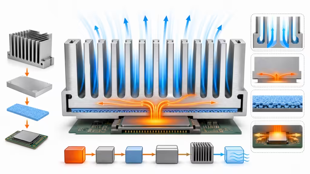
Mounting and TIM: where good heat sinks quietly lose
Mounting is not glamorous, but it decides whether the heat path actually exists.
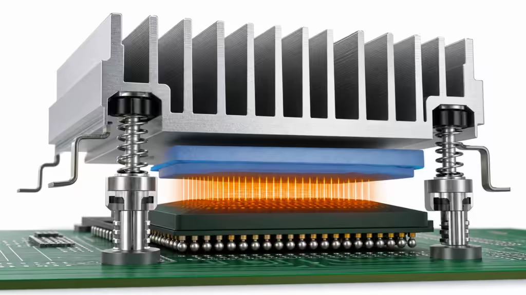
The internal catalogue repeats this point across several product families. BGA heat sinks may use clips, push pins, thermal tape, captive screws, wire clips, or solderless anchors. Some clip designs require minimum chip clearance of 0.3 mm or 0.4 mm above the board. Some require 2.0 mm, 2.5 mm, or 4.5 mm keep-out zones. Push pins have spring constants, force options, and PCB hole requirements.
That is not paperwork. That is thermal performance in mechanical clothing.
TIM choice also matters. First-party materials list thermal pad conductivity >=18 W/mK with 1 to 7 mm thickness and Shore 00 50 hardness, thermal gel conductivity >=16 W/mK, grease conductivity >=7 W/mK, and another material platform with conductivity >=50 W/mK.
Higher conductivity sounds attractive, but it is not the whole story. A stiff high-W/mK pad that does not compress into the gap can perform worse than a softer interface with lower conductivity. Thickness, contact pressure, flatness, pump-out, assembly tolerance, and aging all matter.
Use this mounting checklist:
- Confirm chip height and package clearance.
- Reserve keep-out area before layout freeze.
- Define TIM thickness and compression range.
- Check pressure against package limits.
- Validate after thermal cycling and vibration.
- Test the assembled board, not just the heat sink in isolation.
The heat sink does not cool the datasheet. It cools the assembled mess you actually ship.
Surface treatment and corrosion protection
Most extruded aluminum heat sinks use anodizing for appearance, corrosion protection, and surface durability. Black anodize is common in electronics cooling products and appears repeatedly in the internal catalogue.
Anodizing can also improve radiation behavior, but convection usually dominates in forced-air electronics. Do not pick black anodize because it sounds thermally mysterious. Pick it because it fits the environment, handling needs, corrosion target, and product design.
For harsh environments, also consider:
- Salt spray requirements
- Humidity and condensation
- Galvanic corrosion with screws or copper inserts
- Cleanliness limits
- Electrical grounding or insulation needs
- Adhesive or TIM compatibility
Automotive and industrial materials in the local company files include tests for salt spray, humidity, vibration, high-temperature aging, pressure cycling, leak testing, and cleanliness analysis. That is the right mindset. A heat sink lives in an environment, not a rendering.
When not to use a plain extruded aluminum heat sink
A plain extruded aluminum heat sink may be the wrong answer when heat flux is too concentrated, airflow is unavailable, the enclosure is sealed, the component sits far from the fin field, or the required C/W is below what the profile can deliver.
Move beyond a simple extrusion when:
- The heat load is hundreds of watts in a small area.
- The airflow path cannot reach the fins.
- The junction temperature margin is too small.
- A fan is not allowed.
- The system needs liquid cooling anyway.
- The hot spot must be spread before it reaches the fins.
The company project examples make this boundary visible. A GPU cold plate project at 700 W x 8 GPUs and another at 6,180 W total thermal load are not “just choose a bigger extrusion” problems. They require liquid paths, brazing or skiving processes, manifold thinking, leak validation, pressure drop control, and production discipline.
That is why early thermal architecture matters. If you wait until layout is done, the thermal engineer may still help. They may also stare at the board for a while in the professional silence of someone doing impossible arithmetic.

Selection checklist for precision cooling
Use this checklist before ordering prototypes:
- Define heat load in watts for steady state and transient peaks.
- Set maximum junction, case, or component temperature.
- Measure realistic ambient temperature near the heat sink.
- Estimate airflow through the fins, not just fan free-air CFM.
- Calculate required C/W after upstream thermal resistance.
- Choose fin orientation based on airflow direction.
- Choose width and height based on board and enclosure limits.
- Reserve keep-out for clips, push pins, screws, or wire anchors.
- Choose TIM by total interface resistance, not W/mK alone.
- Validate with thermal resistance, airflow, vibration, thermal shock, and aging tests.
If you are comparing two extruded aluminum heat sinks, do not compare only mass or fin count. Compare the full thermal path under the same airflow condition. A smaller heat sink with better airflow can beat a larger heat sink sitting in stagnant air. Physics enjoys these little plot twists.

FAQ
What is the best aluminum alloy for extruded heat sinks?
AL6063 is one of the most common aluminum alloys for extruded heat sinks because it extrudes well and offers a useful balance of thermal performance, surface finish, cost, and manufacturability. Many BGA plate fin families in the internal catalogue use extruded AL6063 for this reason.
Are extruded aluminum heat sinks better than copper heat sinks?
Not always. Copper conducts heat better, but it is heavier and usually more expensive. Extruded aluminum heat sinks often win when weight, cost, manufacturability, and production scale matter. Copper or hybrid designs make more sense when heat spreading is the limiting factor.
How does airflow affect extruded aluminum heat sink performance?
Airflow can change thermal resistance dramatically. In internal AL6063 BGA heat sink tables, the same 37.5 mm plate fin heat sink moves from 2.0 C/W at 200 LFM to 1.1 C/W at 600 LFM. Always compare heat sinks at the airflow your enclosure can actually deliver.
Is anodizing required for aluminum heat sinks?
Anodizing is not always required, but it is common. It improves corrosion resistance and handling durability, and black anodize is widely used on electronics heat sinks. For forced-air cooling, fin geometry and airflow usually matter more than color.
Can one extruded heat sink cool multiple chips?
Yes, if the base spreads heat well enough and mounting pressure is controlled across all contact points. For multiple hot chips, check base thickness, flatness, TIM stack-up, and hot spot spacing. If spreading resistance is too high, consider a vapor chamber, heat pipe, or copper insert.
When should I choose an active fansink?
Choose an active fansink when passive cooling cannot meet the required C/W within the available footprint. Check fan life, acoustic limits, dust exposure, and failure mode. A fan can solve the thermal target and create a reliability target at the same time.
Final recommendation
For most precision electronics, start with an extruded AL6063 plate fin heat sink and prove the airflow. If the board is dense, use a low-profile or narrow profile. If the heat load rises, move to a wider profile or an active fansink. If the heat flux is concentrated, add spreading with copper, heat pipes, or vapor chambers before jumping to liquid cooling.
The best extruded aluminum heat sink is not the biggest one. It is the one that matches the wattage, airflow, package, mounting method, enclosure, and production process with enough margin left for real life.
For deeper background, read our related guide on aluminum heatsinks: types, function, and efficiency explained. If you are cooling vehicle electronics, the ADAS guide on thermal management for cameras, radar, LiDAR, and domain controllers connects heat sinks to automotive packaging, TIMs, and liquid cooling.
Work with us
We design and manufacture thermal solutions across extruded heat sinks, BGA coolers, thermal interface materials, heat pipes, vapor chambers, liquid cold plates, and validation testing. Our project files include simulation workflows, lab testing, custom materials, and production examples from compact electronics to high-power GPU and automotive modules.
If your current heat sink is running out of margin, send the heat load, package size, airflow target, ambient temperature, and enclosure constraints. We can help turn the thermal problem from “please do not throttle” into a design you can actually build.