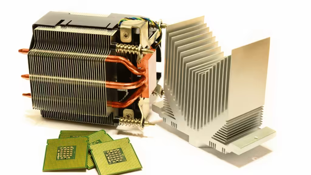
Extruded aluminum heat sinks outperform many alternatives because they balance useful thermal performance, low mass, repeatable geometry, design flexibility, and production economics in one part. They do not always produce the lowest possible thermal resistance. Skived copper, vapor chambers, and liquid cold plates can beat them when heat flux or package density gets nasty. For a large middle band of electronics, however, extrusion solves the whole product problem instead of winning one impressive number on a datasheet.
That distinction matters. A heat sink is not successful because its metal has the highest conductivity or its fins look like a cyberpunk skyline. It succeeds when the component stays below its temperature limit and the part fits the board. The clip must clear nearby components, the fan must push air through the fins, and the manufacturing cost must survive volume production.
Our thermal engineering data make that trade-off visible. They include AL6063 heat sinks tested at 200, 400, and 600 LFM, BGA clip clearances down to 0.3 mm, and a 14.48 mm PCIe height limit. Our lab has 58 sets of professional test equipment. An Ansys, Fluent, and Flotherm workflow has shortened the design cycle by 50%. Those numbers give us something better than “aluminum is good at heat.” They give us boundaries.
This guide explains where extruded aluminum heat sinks win, where they lose, and how to choose without asking a single C/W value to do the work of an entire engineering team.

Quick answer: why do extruded aluminum heat sinks outperform others?
Extruded aluminum heat sinks usually win when a product needs moderate to high air-cooling performance, a constant cross-section, low weight, repeatable production, and enough volume to justify a profile or use a standard one. Alloy 6063 is especially common because it extrudes well, supports thin-fin profiles, accepts anodizing, and transfers heat effectively.
The Aluminum Extruders Council lists AA6063 as a common alloy for heat sinks and electronics housings. Its guidance also makes a useful point: stronger alloys can be harder and more expensive to extrude, while geometry can often deliver the needed structural performance.
In practical terms, extrusion offers six advantages:
- It creates the base and fins as one continuous profile.
- It puts material where the thermal and mechanical design needs it.
- It scales well when the cross-section stays constant.
- It supports cutting, drilling, tapping, anodizing, clips, push pins, and TIMs.
- It has a strong conductivity-to-weight ratio.
- It gives engineers many standard and custom profiles without forcing every project into machined billet.
The last advantage is less glamorous than conductivity, but it pays rent. A thermally perfect concept that cannot be built, mounted, or purchased at the target volume is a very expensive desktop ornament.
What “outperform” should mean in thermal design
Outperformance is not one material property. It is the lowest-risk route to the required component temperature at the required cost, mass, size, and production volume.
Use this scorecard before comparing manufacturing methods:
| Decision factor | Question to answer | Why extrusion often scores well |
|---|---|---|
| Thermal resistance | What Theta_SA is required at the real airflow? | Many AL6063 profiles have cataloged forced-air data |
| Heat spreading | Is the source small relative to the base? | Base thickness can be adjusted, and heat pipes can be added if needed |
| Airflow | Is air linear, mixed, or nearly absent? | Plate fins work well with directed flow; pin or cross-cut options cover mixed flow |
| Package space | What are the footprint, height, and keep-out limits? | Profiles can be cut to length and paired with low-profile clips |
| Mass | Can the PCB or enclosure carry a heavy copper part? | Aluminum density keeps mass and board loading down |
| Production volume | Is this a prototype, 100 units, or 100,000 units? | Standard profiles and repeated cuts favor extrusion |
| Secondary work | Are holes, pockets, or changing cross-sections required? | Light machining is easy; heavy machining can erase the cost advantage |
| Validation | Can performance be simulated and tested under realistic conditions? | Mature profiles and fixtures make comparison and qualification easier |
This is why the phrase “copper conducts better” rarely closes a design review. Copper may conduct heat better, but the finished thermal solution also has a weight, price, airflow path, mounting load, machining plan, and assembly process. Physics brings friends.

Advantage 1: AL6063 balances heat transfer and manufacturability
AL6063 is not the most conductive metal available. It is useful because it combines thermal performance with excellent extrudability, a good surface finish, corrosion resistance, low mass, and familiar finishing processes.
Our 2026-27 product catalog repeatedly specifies extruded AL6063 for BGA, push-pin, active, and DC/DC heat sinks. Its manufacturing summary describes A6063 extrusion as suitable for high-volume production with low non-recurring engineering cost, especially when the part does not need heavy post-machining.
That matches the Aluminum Extruders Council heat sink guidance, which notes that extrusion can place metal where needed and integrate mounting or enclosure functions into a custom profile. A separate AEC heat sink redesign case reports that a 6063 extrusion reduced mass by 47% while increasing surface area by 4% and adding screw ports that removed fabrication steps. That is system-level performance: less material, more useful surface, and fewer assembly operations.
Alloy choice still needs discipline. If the part must carry high mechanical loads, 6061 or another alloy may be a better fit. If the design needs maximum conductivity in a small base, copper may win. For mainstream air-cooled electronics, AL6063 usually gives enough thermal conductivity without turning the part into a dense, expensive brick.
Advantage 2: real thermal performance improves sharply with airflow
Extruded heat sink performance is predictable only when airflow is specified. A C/W value without LFM, inlet temperature, orientation, and test setup is not a specification. It is a rumor with units.
Our product catalog provides a useful forced-air example. In the HS1800 extruded AL6063 plate-fin family, every listed part is 12.7 mm high, while width and mass increase with BGA size.
| BGA size | Part | Height | Weight | 200 LFM | 400 LFM | 600 LFM |
|---|---|---|---|---|---|---|
| 21 mm | HS1800EB | 12.7 mm | 8.5 g | 6.7 C/W | 4.3 C/W | 3.4 C/W |
| 35 mm | HS1807EB | 12.7 mm | 19.8 g | 2.9 C/W | 1.7 C/W | 1.3 C/W |
| 45 mm | HS1811EB | 12.7 mm | 31.1 g | 2.1 C/W | 1.2 C/W | 0.9 C/W |
The table shows two effects. More footprint provides more surface and spreading area. More airflow lowers thermal resistance across each size. The 21 mm part improves from 6.7 C/W at 200 LFM to 3.4 C/W at 600 LFM. The metal did not change. The boundary condition did.
Another low-profile AL6063 example uses a 37.5 mm footprint, 12.7 mm height, and 23.4 g mass. Its listed Theta_SA is 2.0 C/W at 200 LFM, 1.3 C/W at 400 LFM, and 1.1 C/W at 600 LFM.
These values are reference data, not universal promises. The catalog itself warns that actual performance varies by application. A good validation plan recreates the board, TIM, mounting pressure, ducting, obstruction, fan curve, ambient temperature, and heat-source footprint. The wind tunnel number is a starting point. Your enclosure gets the final vote.

Advantage 3: one profile can serve many lengths and power levels
Extrusion creates a continuous constant cross-section. The manufacturer can cut that profile into different lengths, then add holes, tapped features, pockets, clips, anodizing, or thermal interface material.
This makes extrusion particularly effective when several products share a thermal architecture. One profile may support different board widths, LED lengths, power modules, or enclosure sizes. The tooling cost is spread across the family, while cutting and secondary operations handle the variation.
The caveat is simple: the cross-section must remain constant along the extrusion direction. Deep undercuts, changing fin heights, internal pockets, and complex three-dimensional features require machining, joining, casting, forging, skiving, or a hybrid process.
The AEC design guidelines recommend balanced walls, manageable tongue ratios, generous transitions, and geometry that suits available press sizes. Those are not aesthetic rules. They improve straightness, die life, yield, and cost.
An extruded heat sink outperforms a machined one when most of the shape comes free from the die and post-machining stays light. If half the extrusion ends up as chips on a CNC floor, the business case has wandered off without leaving a note.
Advantage 4: mounting and TIM options are production friendly
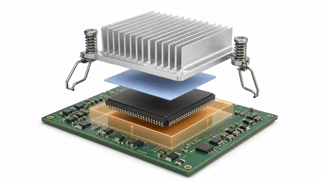
Thermal resistance does not stop at the heat sink base. The interface stack includes package flatness, TIM conductivity, bond-line thickness, mounting pressure, clip geometry, PCB deflection, and assembly variation.
Our BGA catalog shows how closely thermal and mechanical design interact:
- One AL6063 series needs at least 0.4 mm of chip clearance above the board and a 2.5 mm keep-out area around the package.
- A low-profile series supports 0.3 mm chip clearance but requires 2.0 mm keep-out on the length side and 4.5 mm on the width side.
- Push-pin plate-fin parts recommend 3 mm PCB holes.
- Several families offer preassembled clips and thermal pads to reduce assembly variation.
These details can decide a project before the thermal model finishes solving. A heat sink that clears the chip but collides with a capacitor is not “almost compatible.” It is a metal object in the wrong place.
Our materials program adds another layer of practical data. It includes thermal pads at >=18 W/mK with 1-7 mm thickness and Shore 00 hardness of 50, thermal gel at >=16 W/mK, and thermal grease at >=7 W/mK. A high-conductivity composite material reaches >=50 W/mK.
Do not rank those materials by conductivity alone. A softer 16 W/mK gel may outperform a stiffer 18 W/mK pad if it fills the real gap with less contact resistance. A 50 W/mK material can still lose if its bond line is too thick. Conductivity gets the first interview. Compression, thickness, reliability, dispensing, rework, and electrical requirements decide who gets hired.
Advantage 5: extrusion fits real electronics packaging
Extruded profiles are common because electronics products are full of repeated rectangular constraints. BGA packages, DC/DC bricks, LED rails, power modules, and card-level systems all benefit from a base plus parallel fins.
BGA and board-level cooling
Low-profile AL6063 plate fins work well when airflow runs along the channels. Catalog families cover many BGA sizes with multiple heights, clips, tape, and TIM options. This gives a designer a known starting point instead of a blank CAD file and an optimistic afternoon.
DC/DC converter cooling
Our catalog includes quarter-brick, half-brick, and full-brick heat sinks in AL6063 or 356.0 aluminum. Plate fins are recommended for linear airflow, while round pins suit air that arrives from several directions.
That distinction is important. Fin count alone does not make a heat sink efficient. Air must reach the surface and leave the channel. Straight fins placed across the main flow can become a very orderly wall.
PCIe cooling
PCIe cards make the packaging case even clearer. The catalog states a 14.48 mm card height restriction and notes that a typical BGA package consumes about 3 mm of that space. Several listed fansinks therefore stay around 10.5-11 mm high.
One 5 V WV05L and one 12 V WV12L configuration each use a 50 x 65 mm footprint, an 11 mm heat sink height, and a listed thermal resistance of 1.1 C/W. The same page offers extrusion or skiving, aluminum or copper, and push-pin or tape mounting.
This is a good example of honest engineering. Extrusion is one strong option, but the package can force a skived or copper design when the power density climbs. The available height is physics wearing a very small hat.
Advantage 6: simulation and validation reduce development risk
Extrusion is mature, but mature does not mean automatic. Fin pitch, base thickness, airflow bypass, contact resistance, fan operating point, and obstruction can still surprise a design team.
Our engineering workflow uses Ansys for mechanical analysis, Fluent for fluid analysis, and Flotherm for thermal analysis. Optimization with this toolchain has shortened the development cycle by 50%.
Simulation helps answer the questions that a catalog cannot:
- Does the fan deliver its rated flow after system pressure loss?
- Does air bypass the outer fins?
- Is the base thick enough to spread a concentrated source?
- Will the clip bend the PCB or lose contact after cycling?
- Which fin pitch performs best at the actual LFM?
- Does a taller profile improve cooling enough to justify its mass and height?
Our lab has 58 sets of professional test equipment, a 2,000 square meter testing area, and a 10-person test team. Test coverage includes flow and thermal resistance, sealing, pressure, mechanical properties, failure analysis, vibration, thermal shock, humidity, salt spray, high-temperature aging, cleanliness, and welding performance.
That scope matters because cooling hardware fails in more ways than “too hot.” Clips relax. TIM pumps out. Anodized surfaces scratch. Fans load with dust. Brazed joints leak. Boards bow. Thermal cycling takes every weak assumption and adds overtime.

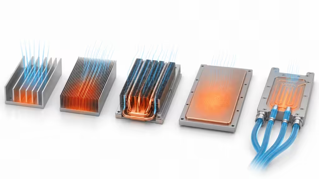
Extruded vs. skived, cast, forged, machined, and liquid-cooled heat sinks
No manufacturing method wins every column. The right question is which process satisfies the thermal target with the least system penalty.
| Method | Where it wins | Where it loses | Production note |
|---|---|---|---|
| Extrusion | Constant profiles, low mass, high volume, light machining, standard families | Fin and cross-section limits | A6063; low NRE at volume; strongest economics without heavy post-machining |
| Skiving | Very thin fins, dense surface area, copper or aluminum | Slower process, fragile fins, geometry and handling limits | Fins as thin as 0.008 inch; base and fins remain one material block |
| Die casting | Complex three-dimensional bases, bosses, pin fins, enclosure integration | Alloy conductivity and porosity need control | Special cast alloy listed at 160 W/mK; strong for complex shapes |
| Forging | Round, elliptical, or mixed fins; high aspect ratios | Tooling and geometry constraints | Aspect ratio up to 35:1; AL6063 or CU11000 options |
| Machining | Prototypes, pockets, changing geometry, detailed features | Material waste and cycle time at volume | No NRE and quick-turn prototyping; aluminum 6061 or copper 1100 |
| Heat pipe or vapor chamber hybrid | Spreads a concentrated source into a larger fin field | Added interfaces, joining, cost, and reliability work | Heat pipes move heat to a better location; vapor chambers spread heat across the base |
| Liquid cold plate | Very high heat flux and multi-kilowatt assemblies | Pumps, leaks, fittings, pressure drop, cleanliness, service | Used in a 6,180 W GPU cold-plate program |
Extrusion wins the broad middle. Skiving wins when fin density matters more than throughput. Casting wins when the heat sink must also be a complex housing. Machining wins early prototypes and irregular features. Forging handles pin geometries and high aspect ratios. Two-phase spreaders and liquid cooling take over when an aluminum base cannot move concentrated heat fast enough.
This comparison also explains why “aluminum vs. copper” is incomplete. The manufacturing route changes the available geometry. A well-designed extruded aluminum profile can beat a poorly ventilated copper block. A skived copper sink can beat an extrusion in a tight high-flux package. The test setup decides which part wins.

Where extruded aluminum heat sinks do not outperform
An honest design guide needs a clear exit ramp. Do not force extrusion into a job because the title of this article sounds confident.
Extreme fin density in a small volume
Our manufacturing data list skived fins as thin as 0.008 inch. That geometry can place much more surface area inside a tight footprint than conventional extrusion. Skiving becomes attractive for compact high-airflow electronics, especially when a taller or wider extrusion will not fit.
Heat must spread far from a tiny source
A concentrated processor can heat the center of an aluminum base while the outer fins stay underused. A thicker base helps, but it adds mass and may still leave too much spreading resistance. Embedded heat pipes or a vapor chamber can move heat across the base more evenly.
Air cooling has reached its practical limit
One anonymized H800 cold-plate project handled eight 700 W GPUs plus four 135 W switches. A separate H100 project reached 6,180 W and used aluminum cold plates with skiving plus brazing.
Those programs did not need a heroic extrusion. They needed liquid cooling, manifolding, fittings, tubing, pressure-drop control, leak integrity, and production validation. At multi-kilowatt rack power, pretending that a larger air-cooled profile will save the day is how meetings become incident reports.
The part needs complex geometry at low volume
If a prototype needs pockets, stepped bases, side holes, and changing fin regions, machining may be faster and cheaper than custom extrusion tooling. Once the cross-section stabilizes and volume grows, the design can migrate to extrusion with targeted secondary machining.
Airflow changes direction
Parallel plate fins prefer linear flow. Round pins, elliptical pins, cross-cut fins, or forged geometries are safer when air can enter from several directions. Choose the fin field for the system airflow, not for the prettiest rendering.
How to select an extruded aluminum heat sink
Use the following process before requesting a profile or quote.
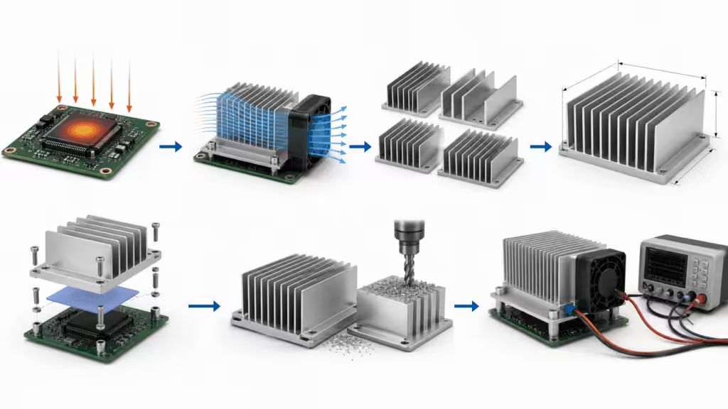
1. Calculate the required thermal resistance
Start with the maximum allowable junction temperature, local ambient temperature, and total device power:
Theta_total_required = (Tj_max - T_ambient_local) / power
Then subtract junction-to-case and interface resistance:
Theta_SA_required = Theta_total_required - Theta_JC - Theta_interface
Use the air temperature at the heat sink inlet, not the room temperature. A card buried behind two upstream processors may inhale preheated air. The office thermostat will not testify on its behalf.
2. Define airflow as a system value
Record LFM through the fin channels or a validated CFM plus flow area. Include filters, grilles, cables, adjacent cards, and fan pressure curves. Free-air fan ratings are generous because free air has never met your enclosure.
3. Match fin geometry to flow direction
Use plate fins for directed linear airflow. Consider round pins, elliptical pins, or cross-cut fins for mixed or multidirectional flow. Check pressure drop as well as thermal resistance.
4. Choose the footprint before chasing fin height
Wider bases improve heat spreading and surface area, but they can block airflow or nearby components. Taller fins can help, but their tips contribute less if conduction along the fin is weak or air never reaches them.
The catalog data makes this visible. A 15 mm aluminum elliptical family improves as height rises from 11.3 mm to 22.3 mm, but the gain is gradual. At 200 LFM, listed thermal resistance moves from 8.51 to 7.18 C/W. At 600 LFM, it moves from 5.84 to 4.82 C/W. Twice the height does not deliver twice the cooling. Thermal design refuses simple motivational slogans.
5. Design the mounting stack early
Reserve clip keep-out zones, PCB holes, spring travel, and tool access before layout freeze. Define TIM type, nominal gap, compression, flatness, and surface finish. Check board strain and serviceability.
6. Decide whether the profile is standard, modified, or custom
Use a standard profile for prototypes and moderate volumes when it meets the envelope. Modify it with cut length, holes, pockets, or anodizing when the cross-section already works. Order a custom die when volume, assembly consolidation, or thermal performance justifies it.
7. Simulate, prototype, and test
Use CFD and thermal simulation to narrow the design space. Prototype with standard profiles or machining. Then test at minimum and maximum airflow, worst-case ambient, realistic mounting pressure, and aged TIM conditions.
Practical application guide
| Application | Best starting point | Upgrade path if margin is poor |
|---|---|---|
| BGA, FPGA, or network ASIC | Low-profile AL6063 plate-fin extrusion with clip and TIM | Taller profile, more airflow, active fansink, or skived fins |
| DC/DC converter | Quarter-, half-, or full-brick AL6063 plate fins for linear flow | Round pins for mixed flow, taller sink, or baseplate cooling |
| PCIe card | Low-profile extruded fansink within the 14.48 mm card envelope | Skived aluminum or copper, ducted chassis airflow |
| LED fixture | Custom 6063 extrusion that also acts as the housing | Wider fin field, improved natural-convection orientation |
| Industrial drive | Wide extrusion with machined mounting surfaces | Heat pipes, fan tray, or liquid cold plate |
| Automotive controller | Extruded or cast enclosure heat sink with validated TIM stack | Heat pipe, vapor chamber, or liquid cooling for high-power SoCs |
| Multi-kilowatt compute | Do not start with a passive extrusion | Cold plates, manifolds, coolant distribution, and leak validation |
For a deeper comparison of manufacturing families, read Aluminum Heatsinks: Types, Function, and Efficiency Explained. For profile-level choices, the related guide Top 10 Extruded Aluminum Heat Sinks for Precision Cooling covers BGA, PCIe, DC/DC, wide, active, and hybrid designs.
FAQs about extruded aluminum heat sinks
Are extruded aluminum heat sinks better than copper heat sinks?
They are better for many products when weight, cost, profile flexibility, and volume matter. Copper conducts heat better, but it is denser and harder to process economically. Use copper or an aluminum-copper hybrid when the thermal gain justifies the mass and cost.
Are extruded heat sinks better than skived heat sinks?
Extrusions usually win on production efficiency, repeatability, and cost for moderate thermal loads. Skived heat sinks can use much thinner and denser fins, so they often win on cooling density in tight high-airflow packages.
Why is 6063 aluminum used for heat sinks?
6063 offers a strong mix of extrudability, thermal conductivity, surface finish, corrosion resistance, and low mass. It supports thin-fin profiles and anodizing without demanding the processing cost of a stronger but less extrudable alloy.
Does black anodizing make an aluminum heat sink cooler?
Black anodizing improves corrosion resistance, electrical isolation at the surface, and radiative emissivity. Radiation can help in natural convection, but airflow and convective surface area usually dominate forced-air electronics cooling. Anodizing does not rescue poor fin geometry or blocked airflow.
How much does airflow change extruded heat sink performance?
It can change performance substantially. In one HS1800 example, a 21 mm AL6063 plate-fin part improves from 6.7 C/W at 200 LFM to 3.4 C/W at 600 LFM. Always compare heat sinks at the airflow your system can deliver.
When should I switch from an extrusion to liquid cooling?
Switch when the required C/W, heat flux, package size, inlet air, or acoustic limit makes air cooling impractical. A 6,180 W GPU program used liquid cold plates because the system had moved far beyond the useful range of a simple passive profile.

The engineering answer
Extruded aluminum heat sinks outperform others when the goal is the best total product result, not the most dramatic material property. They combine useful thermal resistance, low mass, scalable profiles, familiar finishing, practical mounting, and production economics across BGA, PCIe, DC/DC, LED, industrial, and enclosure cooling.
They also have clear limits. Skiving provides denser fins. Copper improves conduction. Casting and forging create geometries that extrusion cannot. Heat pipes and vapor chambers improve spreading. Liquid cooling takes over at very high heat flux and system power.
The useful next step is not to ask, “Which heat sink is best?” Send the thermal team the heat load, allowable component temperature, local ambient, and airflow. Add the footprint, height limit, mounting constraints, and production volume. With those inputs, simulation and physical testing can tell you whether a standard AL6063 profile, a modified extrusion, or a different cooling architecture belongs in the product.