
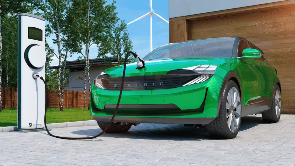
ADAS thermal management is the practice of controlling heat in cameras, radar, LiDAR, electronic control units, and central compute modules so driver-assistance functions stay accurate, reliable, and safe.
That sounds tidy. The hardware is not tidy.
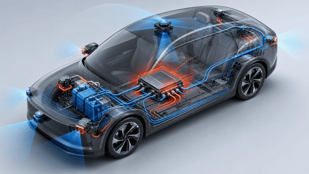
Modern ADAS no longer means one lonely camera staring through the windshield. It can mean multiple cameras, corner radars, front radar, LiDAR, ultrasonic sensors, a cockpit-domain or driving-domain controller, and a central computer that quietly eats watts while pretending to be a polite black box.
Heat is where the polite act ends.
NHTSA describes driver assistance technologies as systems that can warn drivers, support braking or steering, and help reduce crash risk. That puts thermal design in an awkward but important position: if the electronics drift, throttle, fog, misread, or fail, the “assistance” part starts doing a software demo in the wrong room.
This guide explains how to think about ADAS thermal management in 2026. We will cover cameras, radar, LiDAR, ECUs, domain controllers, TIMs, cold plates, EMI, radomes, testing, and manufacturing validation. We will also use anonymized project data from real automotive and electronics cooling programs, because “trust me, bro” is not an engineering method.
Why ADAS Thermal Management Is Getting Harder
ADAS thermal management is becoming harder because sensor count is rising, packages are shrinking, chips are becoming more power dense, and vehicle electronics must survive heat, vibration, humidity, and long service life.
IDTechEx expects automotive demand for cameras, radar, and LiDAR sensors to grow by more than six times by 2033. The same page also notes that ADAS TIM demand may triple within five years, and that today’s typical ECU TIM conductivity of roughly 3-4 W/mK may rise as compute demand increases.
That matches what we see in real projects.
Automotive thermal design now has to handle:
- More sensors per vehicle
- Smaller sensor housings
- More local compute inside sensor modules
- Higher-power SoCs in domain controllers
- Hot parking conditions with little airflow
- Heat soak near engines, brakes, glass, and body panels
- EMI and RF sensitivity in radar
- Vibration, shock, salt fog, humidity, and thermal cycling
- Mass production variation, which is where optimistic CAD models go to learn humility
The painful part is that many ADAS components cannot use a big fan or a thick heat sink. A camera behind glass has optical constraints. A radar needs a radome with the right dielectric behavior. A LiDAR module may have laser-driver heat in a small sealed package. A domain controller may sit in a crowded ECU bay with limited airflow.
This is why ADAS cooling should start at the architecture stage, not after the board layout is frozen and everyone is looking at the thermal engineer like they own a magic wand.

ADAS Heat Sources at a Glance
Here is the practical map.
| ADAS component | Main heat sources | Typical cooling path | Main risk |
|---|---|---|---|
| Camera module | Image sensor, ISP, serializer, power ICs | TIM to housing, metal bracket, local heat spreader | Image noise, focus shift, seal aging, fogging |
| Radar module | RF transceiver, MCU, PMIC, antenna board | TIM to enclosure, heat spreader, conductive housing | RF de-sense, radome loss, thermal drift |
| LiDAR | Laser driver, laser diode, receiver, processor, motor or MEMS driver | Heat spreader, TIM, housing, sometimes liquid or TEC | Laser wavelength drift, lifetime loss, condensation |
| Ultrasonic sensor | Driver electronics, transducer | Housing conduction | Usually lower power, but seal reliability matters |
| ADAS ECU | SoC, memory, PMIC, connectors | TIM, chassis conduction, finned housing, forced air | Hot spots and throttling |
| Domain controller | High-power SoC, memory, Ethernet switch, PMIC, storage | Heat pipe, vapor chamber, fin sink, liquid cold plate | Junction temperature margin, leak risk, serviceability |
The component tells you where the heat starts. The vehicle tells you where the heat can go.
Those are not the same thing.
Cameras: Small Module, Annoying Thermal Details
ADAS cameras usually look thermally harmless. Many are not high-power devices compared with domain controllers.
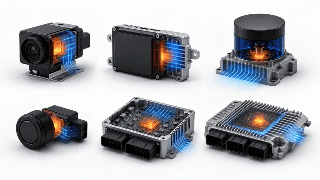
But cameras are sensitive. Temperature can affect image noise, calibration stability, adhesive aging, lens focus, sealing, and fogging. A camera does not need to catch fire to become a problem. It only needs to become slightly unreliable at exactly the worst time.
NHTSA notes that lane departure warning uses a camera to detect lane drift. That is a reminder that camera thermal design supports real safety functions, not just image quality for a dashboard demo.
For camera modules, focus on:
- A clean heat path from sensor board to housing
- TIM thickness control
- Housing flatness and pressure
- Lens and sensor alignment under thermal expansion
- Condensation control
- Validation at hot soak and cold start
- Vibration after thermal cycling
The usual trap is choosing TIM by conductivity alone. A 12 W/mK pad that cannot conform to the gap may perform worse than a softer material with lower conductivity. Thermal resistance, compression, pump-out, outgassing, and aging matter.
The TIM is not a sticker. It is part of the mechanical stack.

Radar: Thermal Design Meets RF Drama
Automotive radar thermal management has one extra complication: the cooling design cannot upset RF performance.
Radar modules include antennas, RF transceivers, MCU or processor logic, power management, shielding, housing, and a radome. Heat must leave the electronics, but the radome must still allow radar signals to pass with low loss and stable behavior.
IDTechEx calls out radar radome and enclosure materials as a dedicated report section, including thermal and dielectric considerations. That split is correct. If a radar housing solves heat but degrades RF performance, it did not solve the problem. It just moved the problem into a more expensive lab.
For radar modules, check:
- Radome dielectric constant and loss tangent
- Water absorption and environmental aging
- Antenna spacing and enclosure tolerances
- TIM placement away from RF-sensitive zones
- EMI shielding without thermal dead zones
- Hot-spot behavior of RF transceivers and PMICs
- Thermal expansion of plastic or polymer enclosures
The key design question is simple: can the radar stay thermally stable while still seeing the road?
That question deserves simulation, RF testing, and thermal cycling. It does not deserve vibes in a slide deck.

LiDAR: Higher Power, Tighter Packaging, Less Forgiveness
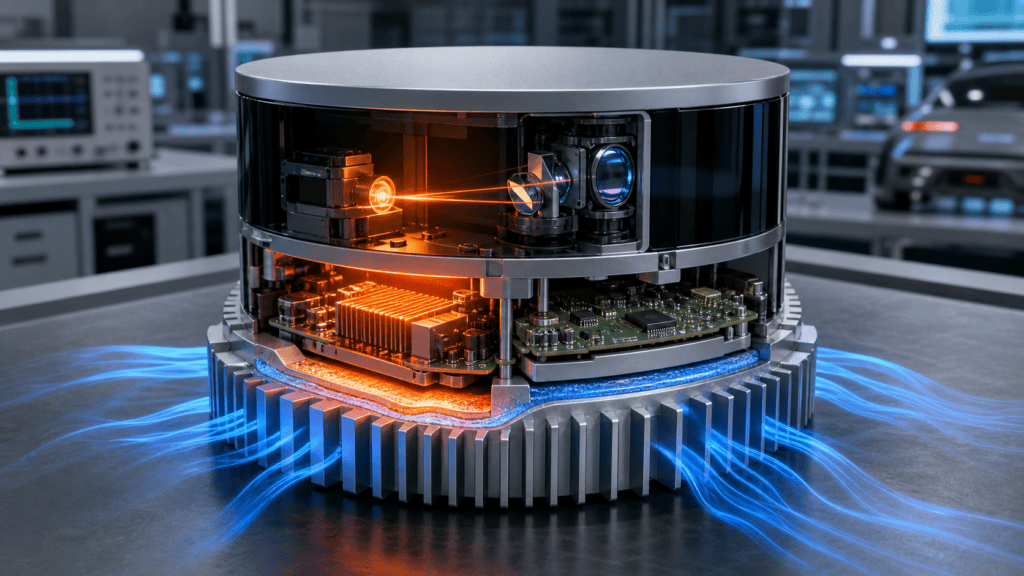
LiDAR thermal management is harder because laser drivers, emitters, receivers, optics, and processing electronics can sit in a compact sealed unit.
The IDTechEx outline points to temperature effects in LiDAR, thermal design for LiDAR units, GaN use in automotive LiDAR, and die attach for laser drivers. That is the right set of headaches.
LiDAR heat can affect:
- Laser wavelength stability
- Optical alignment
- Receiver noise
- Laser lifetime
- Window condensation
- Package stress
- Calibration drift
The cooling path often uses heat spreaders, metal housings, TIMs, and conductive brackets. In some high-power designs, engineers may consider active cooling, thermoelectric cooling, or liquid integration. But every added cooling device adds power, cost, weight, control logic, and failure modes.
So the first rule is boring and useful: move heat passively as far as you can before adding active cooling.
The second rule is even more boring: validate the die attach and package stack under thermal cycling. IDTechEx flags die attach as a reliability topic because repeated heating and cooling can turn tiny package details into field failures.
Tiny cracks do not care that your brochure used a nice gradient.
Domain Controllers: Where ADAS Cooling Gets Serious
Domain controllers and central compute modules are where ADAS thermal management starts looking like server cooling in a car-sized suit.
They may include high-power SoCs, memory, Ethernet switches, PMICs, storage, security modules, and multiple high-speed interfaces. The thermal design may need conduction to the chassis, a finned enclosure, heat pipes, vapor chambers, or liquid cold plates.
In anonymized automotive domain-controller projects from our internal company materials, we saw several useful patterns.
| Project type | Cooling method | Real project data |
|---|---|---|
| Multi-domain controller using an 8797-class SoC | Liquid cooling | Thermal simulation showed Tj = 93.719 C under defined boundary conditions. The design used local dense channels around the SoC and brazable die-cast material with thermal conductivity up to 160 W/mK. |
| J6M-class domain controller | Liquid cooling | Thermal simulation showed Tj = 89.89 C under the project boundary conditions. |
| 8775-class domain controller | Air cooling | Thermal simulation showed Tj = 114.90 C. Component-level limits included 125 C and 150 C ratings in the power map, which left less comfort margin than the liquid-cooled examples. |
| 8295-class domain controller | Air cooling | One production-oriented design used an AlSi10Mn(Mg) die-cast thermal base, copper block, aluminum fins, and a 60W single heat pipe with reflow integration. |
| 8397-class domain controller | Liquid cooling | A design iteration changed the cover from die casting to stamping to reduce cost. The DFM report passed after the redesign. |
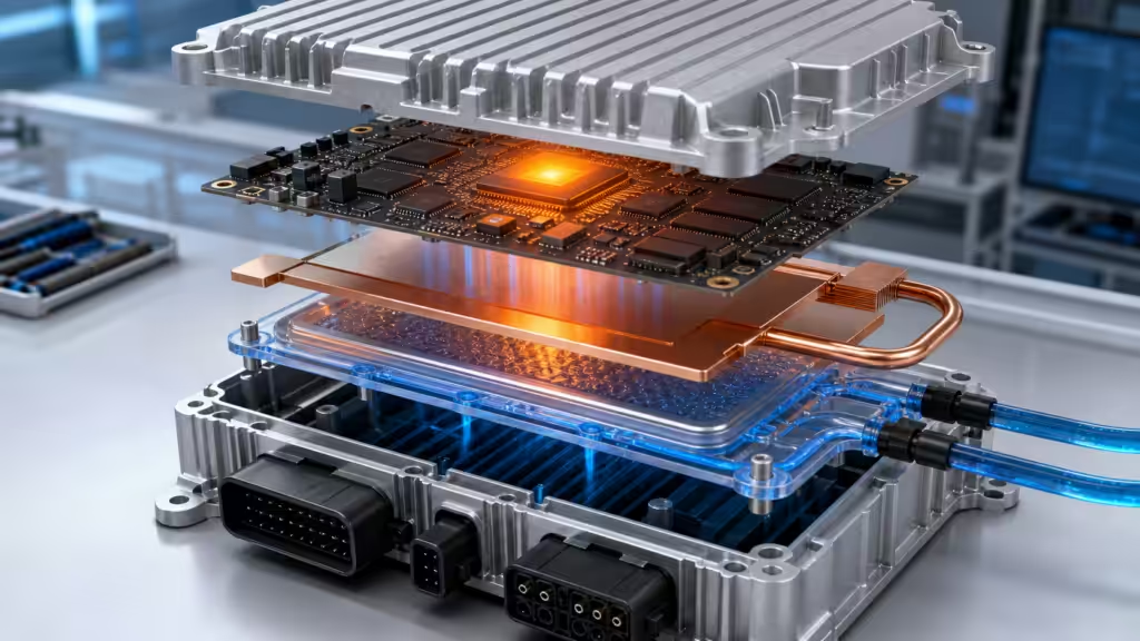
This is where EEAT gets practical.
The difference between air and liquid cooling is not a moral choice. It is a junction-temperature, pressure-drop, packaging, cost, leak-risk, and manufacturing-readiness choice.
Air cooling can work when power density, ambient conditions, airflow, and housing design allow it. Liquid cooling becomes more attractive when the SoC heat flux rises, the enclosure gets cramped, or the target junction temperature margin is too narrow.
But liquid cooling is not a trophy. It is a contract. Once you sign it, you must manage channels, pressure drop, cleanliness, corrosion, leak testing, fittings, assembly torque, field service, and the one tiny bubble that wants to ruin your day.
TIM Selection: Conductivity Is Only the First Interview Question
Thermal interface materials fill gaps between heat sources and heat spreaders. They reduce contact resistance and help heat move into the housing, heat sink, or cold plate.
In ADAS, TIMs may appear between:
- Image sensor boards and camera housings
- Radar PCBs and metal enclosures
- LiDAR laser-driver packages and heat spreaders
- SoCs and ECU lids
- Memory or PMICs and local heat spreaders
- Cold plates and electronic modules
The competitor report highlights TIMs for cameras, radar, LiDAR, and ECUs. That is the right segmentation. Each module has different thermal load, gap, compression, vibration, electrical, and assembly needs.
From internal material programs, we have used or evaluated:
| TIM type | Example project data | Where it can fit |
|---|---|---|
| Thermal pad | Thermal conductivity >= 18 W/mK, thickness 1-7 mm, Shore 00 around 50 | Larger gaps, moderate compression, serviceable assemblies |
| Thermal gel | Thermal conductivity >= 16 W/mK | Irregular gaps, automated dispensing, vibration-sensitive modules |
| Thermal grease | Thermal conductivity around 7 W/mK | Thin bond lines, high contact performance, controlled assembly pressure |
| High-conductivity composite material | Thermal conductivity >= 50 W/mK in one material development deck | Heat spreaders or specialized conduction paths |
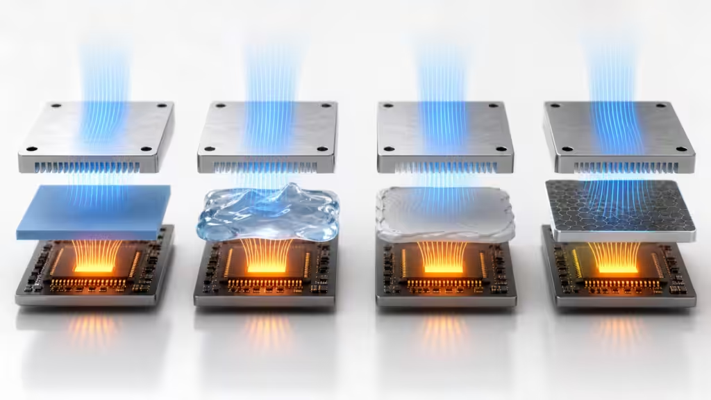
Do not pick TIM by W/mK alone.
Ask these questions:
- What is the real bond line thickness after assembly?
- What pressure is available without bending the PCB?
- Will the TIM pump out under vibration and thermal cycling?
- Does it need electrical insulation?
- Does it outgas near optics?
- Can production dispense or place it repeatably?
- Can the supplier prove aging performance?
The best TIM is the one that works in the actual stack, after assembly, after cycling, and after manufacturing variation has had its coffee.
Air Cooling vs Liquid Cooling for ADAS
The best cooling method depends on heat load, heat flux, location, airflow, enclosure design, temperature target, cost, reliability, and production process.
| Cooling method | Best fit | Advantages | Watch-outs |
|---|---|---|---|
| Housing conduction | Cameras, radar, small ECUs | Simple, sealed, no moving parts | Needs good TIM and flatness |
| Finned enclosure | ECUs, radar, domain controllers | Robust and manufacturable | Airflow may be weak in hidden locations |
| Heat pipe | Hot SoC to remote fin area | Moves heat away from local hot spot | Orientation, integration, vibration |
| Vapor chamber | Thin high-flux spreading | Good for compact controllers | Cost and mechanical constraints |
| Liquid cold plate | High-power domain controllers, central compute | High heat removal and tighter temperature control | Leak risk, cleanliness, pressure drop, fittings |
| Thermoelectric cooler | Special optical or sensor cases | Can control temperature actively | Power draw, heat rejection, control complexity |
| Multifunctional TIM or gasket | Radar, ECU, EMI-sensitive modules | Combines thermal and EMI paths | Must validate both thermal and RF behavior |
Here is the practical rule.
Start with the simplest heat path that meets the junction-temperature target under worst-case conditions. Add complexity only when the data forces your hand.
Your cooling method should earn its place in the vehicle. Fancy cooling that fails validation is just a more expensive way to be wrong.

Liquid Cold Plates for ADAS Domain Controllers
Liquid cold plates are becoming more relevant as ADAS compute consolidates into domain controllers and central computers.
A cold plate usually contains internal channels that carry coolant near the heat source. The design may use skived and brazed copper, aluminum brazing, friction stir welding, laser welding, vacuum brazing, or die-cast and machined structures.
From company production capability data, relevant processes include:
- Skived and brazed cold plates
- Vacuum brazing
- Friction stir welding
- Laser welding
- High-frequency welding
- Reflow welding
- Tunnel-type protective-atmosphere aluminum and copper brazing
- 1000T max die-casting capability
- Machining up to 1600 mm part size
- FAI full-dimensional confirmation
- X-ray inspection for die-cast process confirmation
This matters because liquid cooling is manufacturing-sensitive.
Channel geometry affects pressure drop and temperature uniformity. Brazing quality affects leak risk. Flatness affects TIM performance. Cleanliness affects pumps, filters, and service life. Connector choice affects field reliability.
In other words, a cold plate is not just a pretty metal sandwich. It is a small plumbing system with a silicon landlord.

Testing and Validation: The Part Google Cannot Fake for You
ADAS thermal management needs testing across thermal, mechanical, environmental, electrical, and manufacturing conditions.
In the internal company deck, the lab capability included 58 sets of professional test equipment, a 2,000 square meter test area, and a 10-person professional test team. The listed test scope covered:
- Flow resistance and thermal resistance testing
- Sealing performance testing
- Mechanical performance testing
- Pressure resistance testing
- Product failure analysis
- Welding performance analysis
- Cleanliness analysis
- Rapid temperature change
- Thermal shock
- Alternating damp heat
- Random vibration
- Accelerated shock
- High-temperature aging
- Composite salt spray
- High- and low-pressure airtight testing
- Single-unit and dual-chamber helium leak testing
That list is not glamorous. It is useful.
It also maps well to real ADAS failure modes. Cameras care about humidity and alignment. Radar cares about enclosure stability and EMI. LiDAR cares about thermal cycling and optical reliability. Domain controllers care about hot spots, vibration, and connector integrity. Liquid cold plates care about leakage and cleanliness.
For heat-exchanger production, one deck also recorded helium leak control at 50 ppm and 100% final inspection before customer delivery. For ADAS liquid-cooled modules, that mindset matters. A leak rate is not a decoration in a quality plan. It is the difference between a coolant loop and a slow-motion warranty event.

A Practical ADAS Thermal Design Workflow
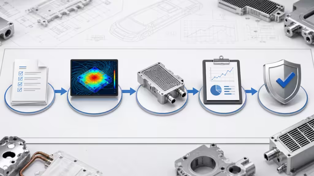
A good ADAS cooling project should move through requirement definition, simulation, prototype testing, design iteration, production validation, and traceable mass production.
Our internal development workflow follows an APQP-style process with design review, sample plans, DFMEA, PFMEA, DFM, BOM, engineering drawings, test plans, control plans, MSA, SPC, PPAP, and lessons-learned output.
Here is the cleaner engineering version.
- Define the thermal target: List power maps, ambient temperature, allowable junction temperature, mounting location, duty cycle, and airflow.
- Map the heat path: Identify every interface from silicon to vehicle body or coolant loop.
- Choose the first cooling concept: Housing conduction, finned enclosure, heat pipe, vapor chamber, cold plate, or hybrid.
- Simulate early: Use CFD and thermal simulation before packaging locks the design into bad choices.
- Build prototypes: Measure flow resistance, thermal resistance, hot spots, pressure drop, and mounting pressure.
- Compare test data with simulation: Update boundary conditions, material assumptions, and contact resistance.
- Run reliability tests: Thermal shock, vibration, humidity, salt spray, pressure cycling, leak testing, and aging.
- Design for manufacturing: Check flatness, welding, brazing, die casting, machining, assembly, cleaning, and inspection.
- Lock the control plan: Use process parameters, inspection points, traceability, and pass/fail thresholds.
- Feed lessons back into the next design: This is how the next project gets faster instead of merely louder.
One internal capability deck states that simulation can shorten the development cycle by 50% when paired with proper validation. The important phrase is “paired with validation.” Simulation without test feedback is a very confident cartoon.
Manufacturing Controls That Matter
ADAS thermal parts often fail because of production variation, not because the concept was absurd.
The company materials show several controls that are directly relevant to ADAS heat sinks, cold plates, and enclosures:
| Manufacturing control | Why it matters for ADAS thermal management |
|---|---|
| MES full-process monitoring | Tracks material, process, equipment, progress, quality, and production data |
| ERP/PLM integration | Keeps design, production, and supply chain data aligned |
| Barcode traceability | Helps isolate quality issues by batch, process, or part |
| 5+2 assembly and inspection lines | Supports assembly, testing, flatness checks, quietness checks, and digital inspection |
| 3,000 square meter cleanroom | Supports cleaner assembly for liquid and electronics cooling parts |
| Helium leak testing | Reduces leak risk in cold plates and heat exchangers |
| FAI and CMM dimensional confirmation | Protects flatness, tolerance, and interface fit |
| Flow and thermal resistance testing | Confirms the part performs, not just looks correct |
For ADAS programs, this is where sourcing teams should slow down.
A supplier that can show a good prototype is useful. A supplier that can repeat the same thermal performance with traceability, inspection, and process controls is more useful. The prototype is the audition. Production is the actual job.

How to Choose an ADAS Thermal Management Supplier
Choose an ADAS thermal management supplier by checking whether they can support architecture, simulation, prototyping, testing, manufacturing, quality control, and cost-down work across the full product life cycle.
Use this checklist:
- Can they read a power map and turn it into a thermal boundary condition?
- Can they run Ansys, Fluent, Flotherm, or similar simulation workflows?
- Can they build prototypes quickly enough for the vehicle program rhythm?
- Can they test flow resistance, thermal resistance, leak rate, vibration, shock, humidity, salt spray, and aging?
- Can they make the part with the same process they will use in mass production?
- Can they support die casting, machining, brazing, friction stir welding, laser welding, and clean assembly?
- Can they provide DFM and cost-down suggestions before tooling gets expensive?
- Can they protect customer confidentiality in case studies?
- Can they show traceability through MES, barcode systems, and quality documentation?
One internal case is a good example: an 8397-class domain controller liquid-cooling design changed from a die-cast cover to a stamped cover to lower cost, and the DFM report passed after the redesign.
That is the kind of supplier behavior you want. Not just “we can cool it,” but “we can cool it, build it, inspect it, and keep the cost from wearing a tiny crown.”
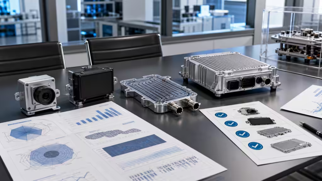
Common ADAS Thermal Design Mistakes
Here are the mistakes that keep showing up.
Mistake 1: Waiting Too Long
Thermal design should start before the PCB, enclosure, and connector layout are frozen. If the cooling path arrives late, it has to sneak through whatever space is left.
That space is usually terrible.
Mistake 2: Using Conductivity as the Only TIM Metric
High W/mK does not guarantee low thermal resistance. Bond line thickness, pressure, compliance, aging, pump-out, and surface roughness can dominate the result.
Mistake 3: Ignoring Stationary Heat Soak
Some sensors sit in hot locations with no active airflow when the vehicle is parked. The worst thermal case may be a stationary car in summer, not highway driving.
Mistake 4: Treating Radar Like a Normal Electronics Box
Radar needs thermal control and RF transparency. Housing and radome choices can change radar performance.
Mistake 5: Adding Liquid Cooling Without a Manufacturing Plan
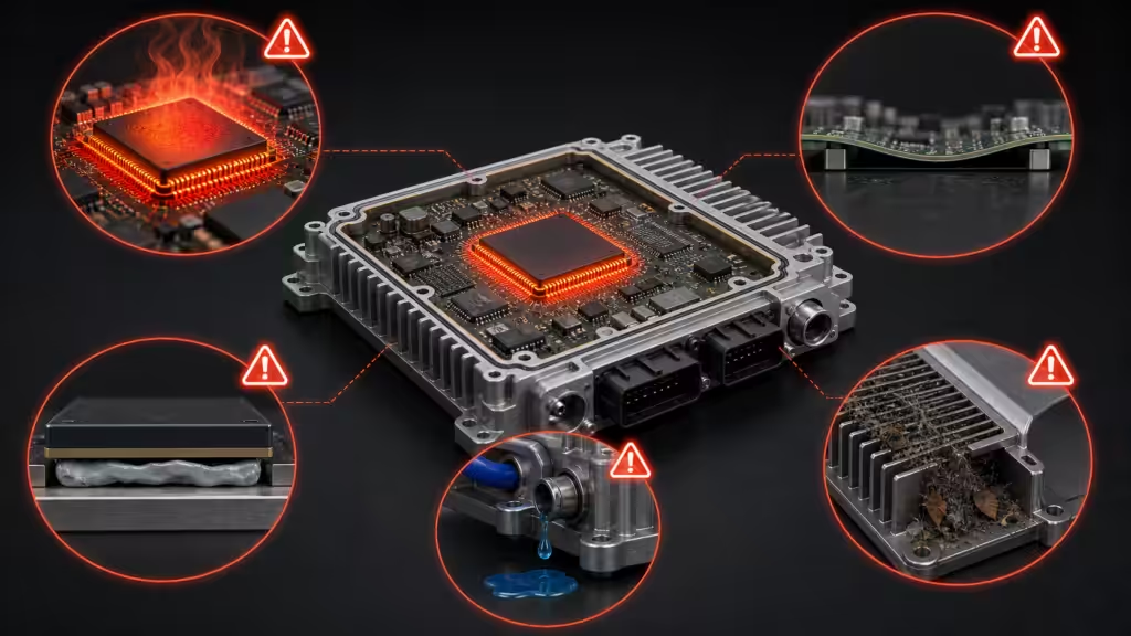
Liquid cooling can solve the temperature problem and create leak, cleanliness, pressure-drop, and service problems. The design is only as good as the production process behind it.
Mistake 6: Trusting Simulation Without Test Correlation
Simulation is powerful. But contact resistance, TIM compression, manufacturing tolerance, and airflow leakage can move real results away from the model.
Measure the hardware. The hardware has opinions.
Quick Decision Guide
Use this as a first-pass decision tool.
| If your ADAS component has… | Start with… | Move up to… |
|---|---|---|
| Low heat load and large metal housing | TIM plus housing conduction | Local heat spreader |
| Camera thermal drift or fogging | Housing conduction, seal design, humidity testing | Better bracket conduction or local heat spreader |
| Radar hot spots and RF sensitivity | Conductive enclosure plus RF-safe radome | Multifunctional thermal and EMI solution |
| LiDAR laser-driver heat | Heat spreader, TIM, housing conduction | TEC or liquid only if passive fails |
| ECU SoC hot spot | TIM plus finned enclosure | Heat pipe or vapor chamber |
| Domain-controller Tj margin below target | Heat pipe, vapor chamber, optimized enclosure | Liquid cold plate |
| Liquid cold plate leak risk | Helium leak testing, cleanliness control | Process redesign before SOP |
This table will not replace engineering. It will keep the first meeting from becoming interpretive dance.

Frequently Asked Questions
What is ADAS thermal management?
ADAS thermal management controls heat in driver-assistance sensors and compute modules, including cameras, radar, LiDAR, ECUs, and domain controllers. It uses TIMs, heat spreaders, housings, heat pipes, vapor chambers, cold plates, airflow, and validation testing to keep electronics within safe operating temperatures.
Why does ADAS need thermal management?
ADAS needs thermal management because sensor accuracy and compute reliability depend on stable electronics. Heat can increase image noise, shift optical alignment, affect radar performance, shorten laser lifetime, throttle processors, age seals, and reduce reliability during hot soak, vibration, humidity, and thermal cycling.
Which ADAS components need cooling?
Cameras, radar modules, LiDAR units, ADAS ECUs, domain controllers, central compute modules, power electronics, memory, PMICs, and communication chips may all need cooling. Low-power sensors may only need housing conduction, while high-power domain controllers may need heat pipes, vapor chambers, or liquid cold plates.
Is liquid cooling necessary for ADAS?
Liquid cooling is not always necessary for ADAS. It becomes useful when a domain controller or central compute module has high heat flux, limited airflow, or tight junction-temperature targets. For many cameras, radar modules, and lower-power ECUs, conduction through the housing may be enough.
What TIM is best for ADAS electronics?
The best TIM for ADAS electronics depends on gap size, pressure, vibration, electrical needs, outgassing limits, aging, and assembly method. High thermal conductivity helps, but low real thermal resistance in the assembled stack matters more than the W/mK number on a datasheet.
How do you validate ADAS thermal parts?
Validate ADAS thermal parts with thermal resistance testing, flow resistance testing, hot-spot measurement, thermal shock, rapid temperature change, vibration, shock, humidity, salt spray, pressure testing, cleanliness checks, and leak testing. Simulation should be correlated with prototype test data before production release.
Final Takeaway
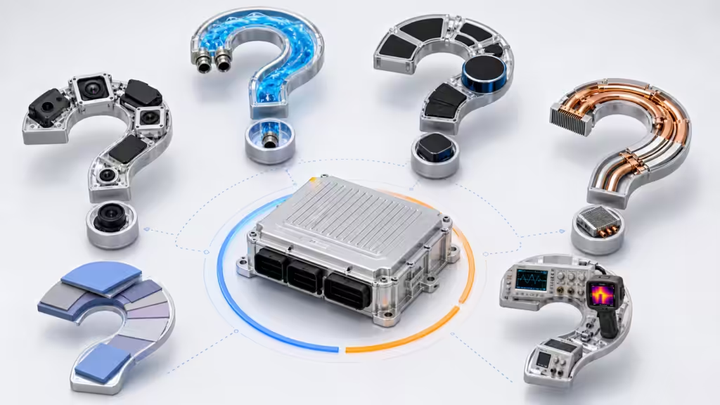
Thermal management for ADAS is no longer a small material decision at the end of the design cycle.
It is part of sensor accuracy, compute reliability, RF performance, manufacturing yield, and long-term vehicle safety. The best designs connect the whole chain: power map, thermal path, material, enclosure, cold plate, test lab, production process, and traceability.
If you are designing cameras, radar modules, LiDAR, ADAS ECUs, or domain controllers, start thermal work early. Bring the thermal engineer into the architecture conversation before the layout becomes sacred geometry.
And when a supplier shows a beautiful simulation, ask for the test report.
The pixels may be pretty. The helium leak tester is less romantic, but it tells fewer lies.