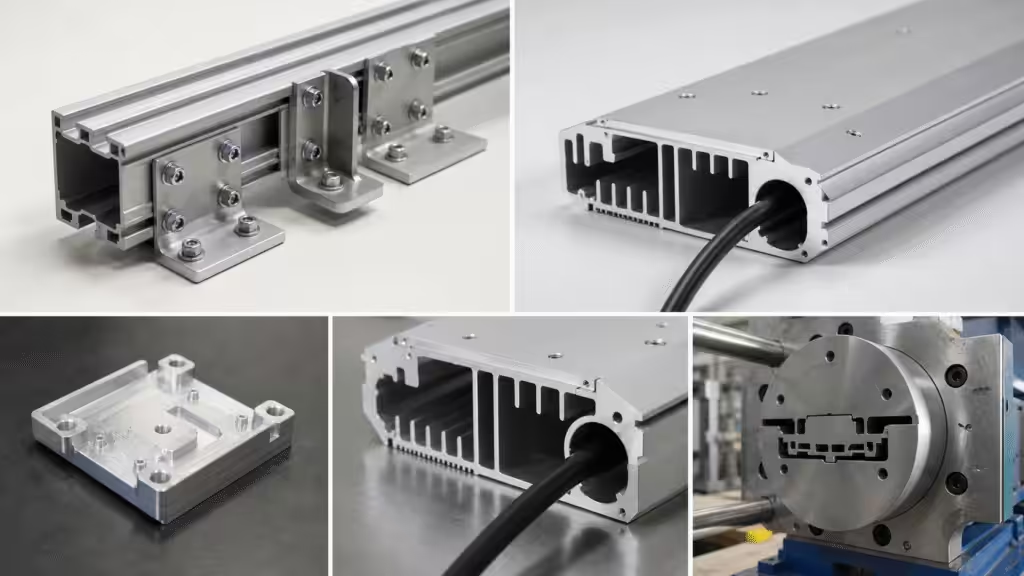
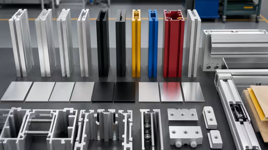
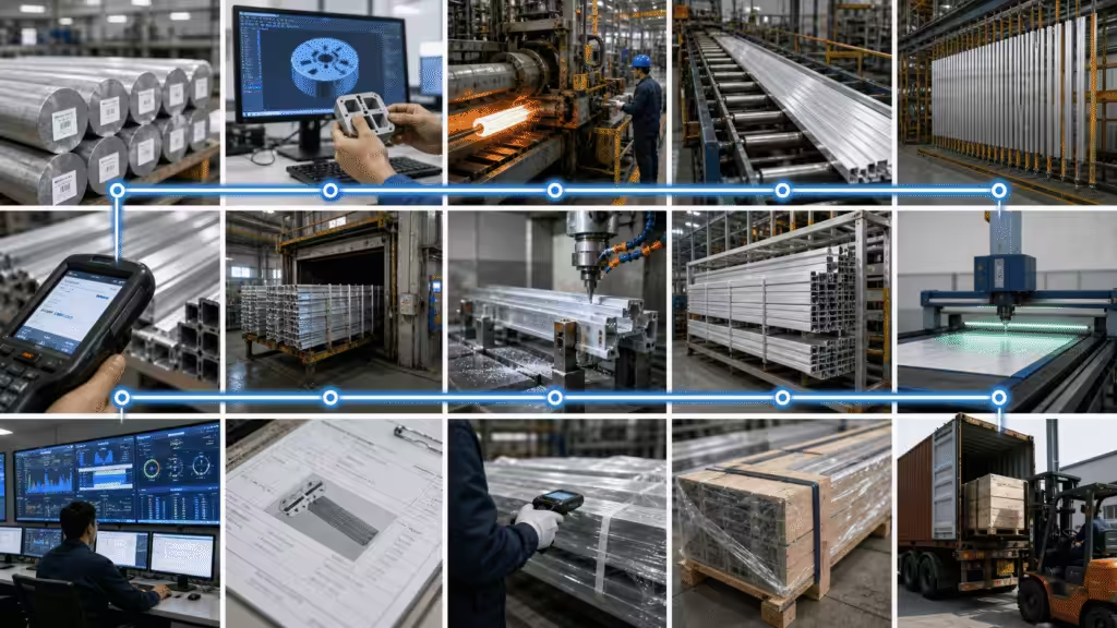
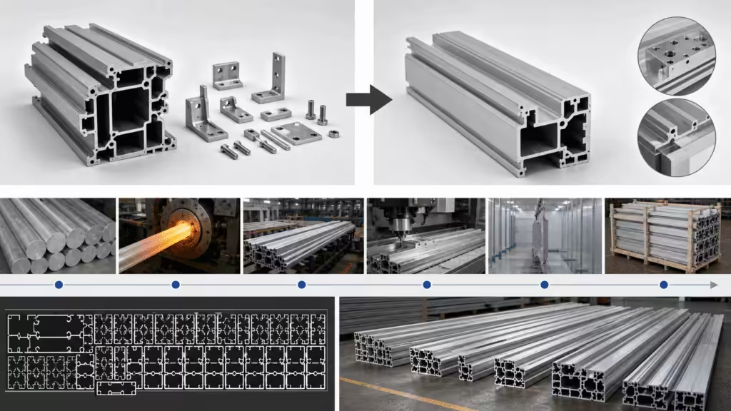
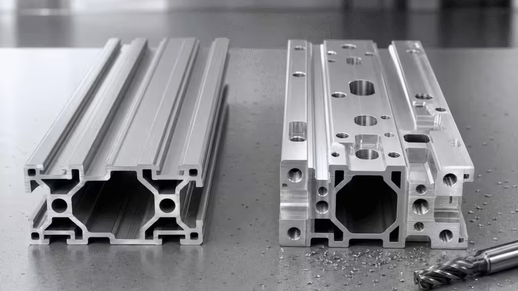
Custom aluminum profiles can turn several brackets, rails, covers, heat-spreading surfaces, and cable paths into one repeatable part. That sounds elegant because it is. It can also turn one vague drawing into several pallets of precisely repeated disappointment.
The difference is not the aluminum alone. It is the chain of decisions behind the profile: functional requirements, cross-section design, alloy and temper, die strategy, extrusion tolerances, machining datums, surface finish, inspection, packaging, and production control.
This guide explains that chain from concept to mass production. It is written for engineers, product teams, and buyers who need custom aluminum extrusion profiles that fit, assemble, and perform after the sample leaves the conference room.
What Are Custom Aluminum Profiles?
A custom aluminum profile is a constant cross-section made for a specific product or assembly. A heated aluminum billet is pushed through a shaped die. The long profile is then cooled, stretched, cut, heat treated, machined, finished, inspected, and packed as required.
The cross-section can include ribs, screw bosses, tracks, grooves, heat-sink fins, wire channels, alignment features, hinge details, and cosmetic faces. Because these features run along the profile, extrusion can create them in one continuous operation.
That is the main economic advantage. You pay for a die and development work, then repeat useful geometry along every meter of material. When the design is stable and volume is suitable, this can remove machining, fasteners, welds, and separate components.
Custom profiles differ from stock angles, channels, tubes, and T-slot rails. Standard sections avoid dedicated tooling and are excellent for prototypes or low-volume builds. A custom section becomes attractive when the same features repeat, downstream work is expensive, or a standard profile wastes space and mass.
Custom does not mean unlimited. The part must still flow through a die, exit without tearing, cool without excessive distortion, straighten without damage, and survive every process that follows. CAD has never met an undercut it did not like. Extrusion tooling is more selective.
When Does a Custom Profile Make Sense?
Choose a custom profile when it removes enough cost, mass, assembly work, or performance risk to justify tooling and qualification.
Good candidates often have:
A stable cross-section over most of the part length
Repeated rails, ribs, grooves, bosses, fins, or cable paths
Enough annual volume to spread tooling and trial costs
Several parts that can become one profile
A need for lower mass than steel or a machined billet
Thermal, electrical, structural, or cosmetic functions in the same section
Secondary machining limited to local holes, pockets, or end features
Stay with a standard profile or a fully machined part when the design is still changing, quantities are very low, features vary constantly along the length, or the project cannot accept a tooling loop.
A hybrid route often works best during development. Machine early prototypes from stock. Freeze the interfaces after testing. Then move the stable geometry into a custom extrusion. This keeps experiments out of hardened tool steel, where edits become slower and invoices develop confidence.
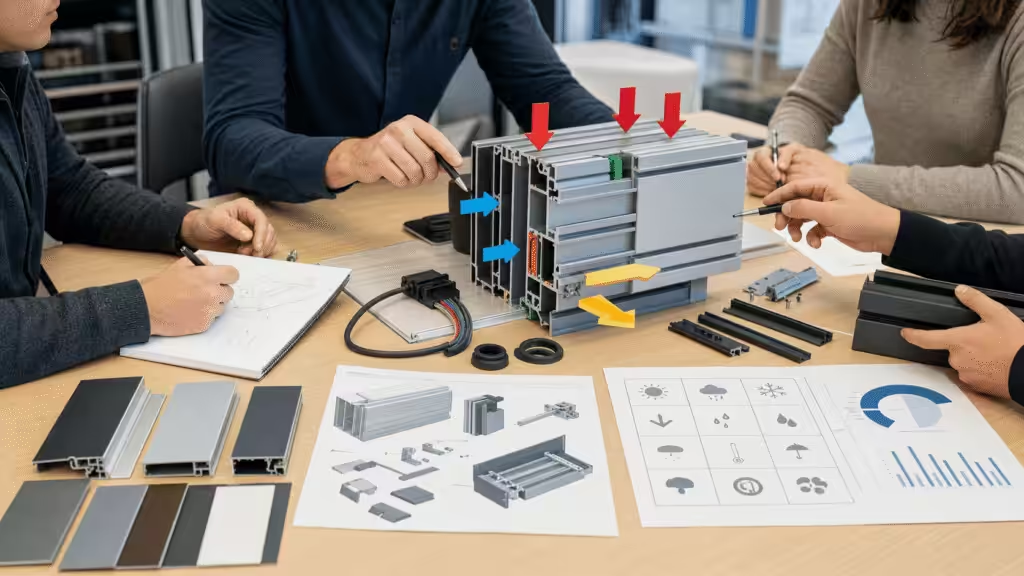
Define the function, loads, environment, interfaces, volume, and target cost.
Design the cross-section for both performance and extrusion.
Select the alloy, temper, and material standard.
Set functional datums and realistic tolerances.
Choose the die type and complete tool design.
Extrude, cool, stretch, age, and correct the trial profile.
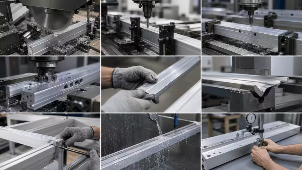
Add cutting, CNC machining, punching, bending, welding, or assembly.
Apply the required finish and protect critical surfaces.
Approve the finished first article, then control repeat production.
Each stage changes the next one. A finish adds thickness. Heat treatment can affect distortion. Machining may release stress. Packaging can damage a cosmetic face that survived every previous operation.
Treat the profile as a finished production component from the first design review. Designing only the cross-section and “adding the details later” is how later becomes expensive.
1. Define Functional Requirements Before Drawing the Profile
Start with the job, not the shape.
List the loads, mounting points, mating parts, temperature range, expected life, corrosion exposure, electrical requirements, cosmetic surfaces, service access, and installation method. Add annual volume and expected program life because a technically elegant profile can still be commercially wrong.
Separate requirements into three groups:
Critical: A failure affects safety, function, sealing, alignment, thermal performance, or regulatory compliance.
Important: Variation affects assembly time, appearance, noise, or serviceability.
Reference: The dimension describes geometry but does not need independent control.
This ranking prevents every dimension from receiving the tightest tolerance available. Precision should follow function. Applying it everywhere is not engineering rigor; it is a subscription plan for higher cost.
Create a boundary-condition sheet for the supplier. Include load directions, restraint points, mating materials, airflow or liquid flow if thermal performance matters, ambient conditions, and the finish state used for fit checks.
Our documented development workflow uses the same logic in thermal programs. It starts with the application scenario, heat-source data, targets, and constraints. It then moves through simulation, prototype testing, data correction, process validation, and production preparation. This sequence matters for profiles too: define the problem before optimizing the metal.
2. Design the Cross-Section for Extrusion
Extrusion design balances function with metal flow. A small change to a wall, rib, void, or radius can improve die life, reduce twist, and lower scrap.
The Aluminum Extruders Council’s design guidance recommends balanced walls, useful symmetry, generous transitions, and restraint with deep narrow tongues or complex hollows. These are not cosmetic preferences. They help the aluminum move through the die at a more even rate.
Keep Wall Thickness Balanced
Use a reasonably uniform wall thickness where the function allows it. Abrupt thick-to-thin transitions can cool at different rates and disturb metal flow. The result may be sink marks, distortion, surface defects, or extra die correction.
When thickness must change, use a gradual transition. Put material where it supports a load path, thread, seal, or heat path. Do not make an entire profile heavy because one screw boss needs more local section.
Minimum wall thickness depends on alloy, profile size, geometry, surface requirements, press capability, and extrusion ratio. A single internet number is not a universal design rule. Ask the chosen extruder to review the complete section.
Use Radii Instead of Sharp Corners
Internal corners should have radii that support metal flow and die strength. Sharp internal corners are difficult to fill and create stress in the tool.
External edges can look sharp while still using a small practical radius. If an exact sharp edge is functional, define why. It may need machining after extrusion.
Control Deep Channels and Tongues
A narrow slot creates a slender section of die steel called a tongue. As the slot gets deeper and narrower, the tongue becomes harder to cool and support. Tool deflection or breakage risk rises.
Open the slot, reduce its depth, add a relief, or divide the function when possible. The profile may gain a fraction of a millimeter and lose a large amount of manufacturing drama.
Treat Hollows as a Tooling Decision
Closed voids usually need a porthole, bridge, spider, or related hollow die. The billet divides around supports inside the die and rejoins before exit. That creates longitudinal weld seams in the extruded profile.
Hollow sections can provide excellent stiffness and integrated passages, but they increase tooling complexity. Discuss pressure, fatigue, leak-tightness, cosmetic requirements, and machining across seam locations before approving the concept.
Add Ribs, Bosses, and Grooves With a Purpose
Ribs can improve stiffness, support flatness, guide assembly, or increase heat-transfer area. Screw bosses can reduce separate hardware. Grooves can hold gaskets, panels, clips, or wires.
Check tool access and mating-part insertion. A feature that works in a clean CAD section may become blocked after anodizing, bow, twist, or a burr enters the tolerance stack.
The AEC also notes that small profile changes can improve extrudability and reduce cost. Ask the supplier to return a marked DFM drawing that explains each proposed change and its effect on tooling, tolerance, finish, or function.
3. Choose the Right Aluminum Alloy and Temper
Do not specify “aluminum” and leave the rest to interpretation. Alloy and temper affect strength, extrudability, corrosion behavior, finish, welding, machining, and thermal performance.
The 6xxx series is common for custom aluminum extrusion profiles because magnesium and silicon give a practical balance of properties and processability.
6063 for Complex or Visible Profiles
6063 is a common starting point for detailed cross-sections, visible surfaces, heat sinks, enclosures, and architectural profiles. Hydro describes 6063 aluminum as a widely used extrusion alloy with reliable extrudability, good surface finish, and good anodizing behavior.
Choose 6063 when extrusion detail and surface consistency matter more than maximum structural strength. T5 and T6 are common tempers, but the correct temper depends on required properties and downstream work.
6061 for Higher Structural Demand
6061 is often selected when strength, machining, or welding has more weight in the decision. Hydro’s 6061 alloy data sheet also notes that 6063 may be preferable when cosmetic anodizing is critical.
6061 can be less cooperative with very intricate sections than 6063. Do not choose it from a familiar part number alone. Confirm that the profile geometry and press route suit the alloy.
Other Useful 6xxx Options
6060 may suit appearance-led profiles with good extrudability. 6005A or 6082 may be considered for higher structural needs, depending on region, section, temper, and supplier capability.
The exact choice should follow calculations and the applicable material standard. ASTM B221 covers aluminum-alloy extruded bars, rods, wire, profiles, and tubes, including chemical composition and mechanical-property requirements for listed alloys and tempers. European projects may instead call out EN standards.
Put the full alloy, temper, governing specification, required properties, and substitution rules on the drawing or purchase specification. “Equivalent material allowed” is an invitation to discover how creative equivalence can become.
4. Set Tolerances That Match Function and Process
Precision manufacturing does not mean placing plus-or-minus 0.05 mm beside every dimension. It means controlling the dimensions that make the product work and choosing the right process for each one.
Separate the drawing into:
As-extruded cross-section dimensions
Length, straightness, twist, flatness, and end squareness
Machined holes, pockets, threads, and datum surfaces
Post-finish dimensions and fit conditions
Assembly-level relationships
Extrusion can hold a consistent cross-section, but long profiles can bow or twist. A CNC machine can create precise local features, but only if the part has stable datums and suitable support.
Build a Datum Strategy
Choose datums from stable functional surfaces. Avoid locating every machined feature from a wall that can move with extrusion variation.
A practical setup might use one broad mounting face as the primary datum, a side wall as the secondary datum, and an end or machined hole as the tertiary datum. The exact scheme depends on how the part locates in the real assembly.
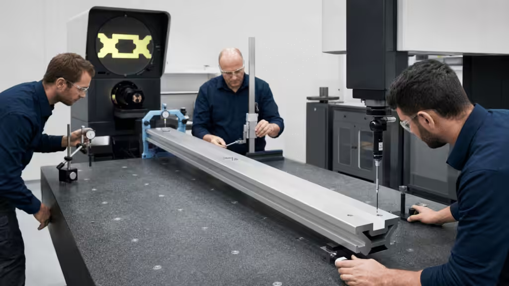
Include datum targets or restraint instructions when a long or flexible profile cannot sit naturally in the inspection setup. Otherwise, the supplier and customer may measure the same good part in two different ways and produce two different verdicts.
Control Straightness, Twist, and Flatness Separately
Straightness describes deviation along the length. Twist describes angular rotation between cross-sections. Flatness controls one surface.
These conditions affect sliding inserts, panel alignment, sealing, machine motion, and cosmetic gaps. State the measurement length, support condition, permitted restraint, and finished state.
Do not assume a short sample proves a long production part. A 100 mm coupon cannot demonstrate the straightness of a three-meter rail, even if it looks deeply committed to quality.
Reserve Tight Tolerances for Critical Features
Use standard extrusion tolerances for noncritical geometry when possible. Add machining only where the functional requirement justifies it.
Examples include:
Bearing seats
Precision linear-rail mounting faces
Seal lands
Connector locations
Hole patterns tied to another assembly
Flat thermal interfaces
The AEC extrusion tolerance resources explain why standard and precision tolerances must be discussed with the extruder. The profile size, wall, alloy, geometry, and measurement method all matter.
Check the Finished Part
Anodizing and powder coating change surface dimensions. Masking leaves transitions. Heat treatment and machining can release stress. Bending changes local geometry.
Define whether each dimension applies before or after finish. Then test the real mating component, gasket, fastener, panel, or slider in the final condition.
5. Plan the Die, Trial, and Prototype Strategy
The die turns the approved cross-section into repeatable geometry. Tool design depends on whether the profile is solid, semihollow, or hollow, plus the alloy, size, weight per length, wall balance, and production rate.
Do not treat the first die trial as final production approval. A trial usually checks metal flow, section dimensions, surface condition, twist, bow, and tool behavior. The die may need correction before it produces an acceptable profile across the intended run.
Define the trial package before the tool is built:
Approved profile drawing and revision
Alloy and temper
Trial length and quantity
Dimensions and characteristics to inspect
Sample locations along the run
Mill-finish and finished sample requirements
Mating-part or assembly tests
Tool-correction approval process
Ownership, storage, maintenance, and replacement terms
For early functional testing, machine a profile-like part from plate or stock. It will not reproduce every extrusion characteristic, but it can verify interfaces, fasteners, clearances, and assembly logic before the custom die exists.
Then inspect the actual extrusion trial. Do not transfer conclusions from a machined prototype to metal flow, weld seams, straightness, or anodized appearance.
Our internal workflow offers a useful benchmark. Simulation with Ansys, Fluent, and FloTHERM shortened the recorded development cycle by 50% in one thermal-development program. That does not promise the same result for every profile. It does show why design analysis before tooling can remove expensive physical loops.
6. Design Secondary Machining Into the Profile
Extrusion creates the continuous geometry. Secondary operations create features that change along the length or need tighter local control.
Common operations include:
Precision sawing and miter cutting
Drilling, reaming, tapping, and counterboring
Milling pockets, slots, notches, and end features
Punching repeated holes
Bending or stretch forming
Welding, fastening, adhesive bonding, and assembly
Deburring, washing, marking, and packaging
Design clamping surfaces and machining datums into the section where possible. Leave tool access around holes and pockets. Avoid thin fins beside heavy cuts if tool pressure or heat may distort them.
Long profiles need support. Ask how the machine fixture controls sag, vibration, and accumulated position error. Also ask how the supplier measures features at both ends and after unclamping.
The order of operations matters. Machining before aging, straightening, bending, or finishing can produce a different result than machining after those steps. Threads may need masking. Bare electrical contacts may need post-finish machining.
Our manufacturing records place extruded and machined parts in the same product matrix, alongside multiple joining processes. That integrated view is useful: the best profile is not the one with the most features. It is the one that leaves the cheapest, most stable secondary process.
7. Choose a Surface Finish That Supports the Product
Surface finish affects corrosion behavior, wear, color, electrical contact, bonding, friction, fit, and handling. Choose it from the application, not from a sample board alone.
Mill Finish
Mill finish may suit hidden indoor parts or profiles that receive later processing. It is the lowest-complexity option, but it does not mean flawless cosmetic appearance.
Define acceptable die lines, pickup, scratches, stains, and handling marks if appearance still matters.
Anodizing
Anodizing grows an oxide layer from the aluminum surface. It can improve corrosion and wear resistance while providing a metallic appearance.
Specify the anodizing standard, type, thickness class, color, gloss, rack-mark locations, sealed condition, and masked areas. The current Qualanod specifications are one recognized reference for sulfuric-acid anodizing quality requirements.
Remember that anodizing can affect tight fits and electrical contact. Confirm sliding tracks, threads, grounding faces, adhesive areas, and cosmetic limits after treatment.
Powder Coating
Powder coating offers a wide color and texture range and a thicker finish. That thickness can close narrow gaps, fill corner details, and change snap fits.
Call out masking and critical openings. Use approved color and texture samples under agreed lighting.
Mechanical Finishes
Brushing, blasting, tumbling, and polishing change surface texture. They may happen before anodizing or coating.
Define the grain direction and visible faces. Then protect those faces through machining, inspection, and transport. A perfect brushed finish has limited value after two long profiles share a truck without separators.
8. Validate the Finished Profile Before Mass Production
Approve the part that production will ship, not only the mill-finish extrusion.
A finished first-article inspection should cover:
Material certificate and lot traceability
Cross-section dimensions
Wall thickness and profile form
Cut length and end squareness
Straightness, twist, and flatness
Machined features and threads
Finish type, thickness, color, and cosmetic limits
Mating-part and assembly tests
Packaging and label approval
Drawing revision and process route
Use the actual inspection method planned for production. A first article measured by a senior engineer on special equipment may not predict a process checked with a different fixture at line speed.
Our internal laboratory records list 58 sets of professional test equipment across 2,000 square meters, supported by a 10-person test team. The documented scope includes mechanical tests, failure analysis, thermal shock, rapid temperature change, humidity, vibration, high-temperature aging, salt spray, cleanliness, sealing, and flow or thermal resistance tests.
Not every custom aluminum profile needs this menu. A decorative trim does not require thermal shock because the lab owns a chamber. Match validation to failure risk.
For an industrial rail, proof load, straightness, fastener pull-out, vibration, and assembly cycling may matter. For an enclosure, focus on fit, finish, sealing, corrosion, and electrical continuity. For a heat-sink profile, verify base flatness, machining, airflow conditions, mounting pressure, and thermal performance.
This risk-based approach is stronger than adding tests by habit. Test the ways the product can actually fail.
9. Control Repeat Production With Traceability
A golden sample proves one part passed. Precision manufacturing must explain why the next lot should pass too.
Build a control plan around the characteristics that matter. Link each one to a process step, inspection method, sample rate, reaction plan, and record.
Useful traceability can connect the shipped part to:
Billet or material lot
Alloy and temper records
Die number and revision
Extrusion and aging batch
Cutting and machining program revision
Tool or fixture identity
Finish batch and color reference
Inspection and first-article reports
Packaging lot and shipment
Our production records describe MES monitoring of equipment and process parameters, production progress, material and process history, quality controls, scheduling, and ERP/PLM integration. Separate records list barcode traceability and automatic flatness inspection in an adjacent assembly environment.
These controls do not make defects impossible. They make containment and root-cause work faster when reality ignores the slide deck.
Also require change notification. A replacement die, new billet source, different press, revised CNC fixture, new anodizing line, or moved production site can change the finished part. Define which changes need approval and whether a new first article is required.
An ISO 9001 certificate can support the quality-system review. ISO explains that ISO 9001 defines requirements for a quality management system, but it does not prescribe one operating method. Audit the process that will make your part, not the certificate frame in reception.
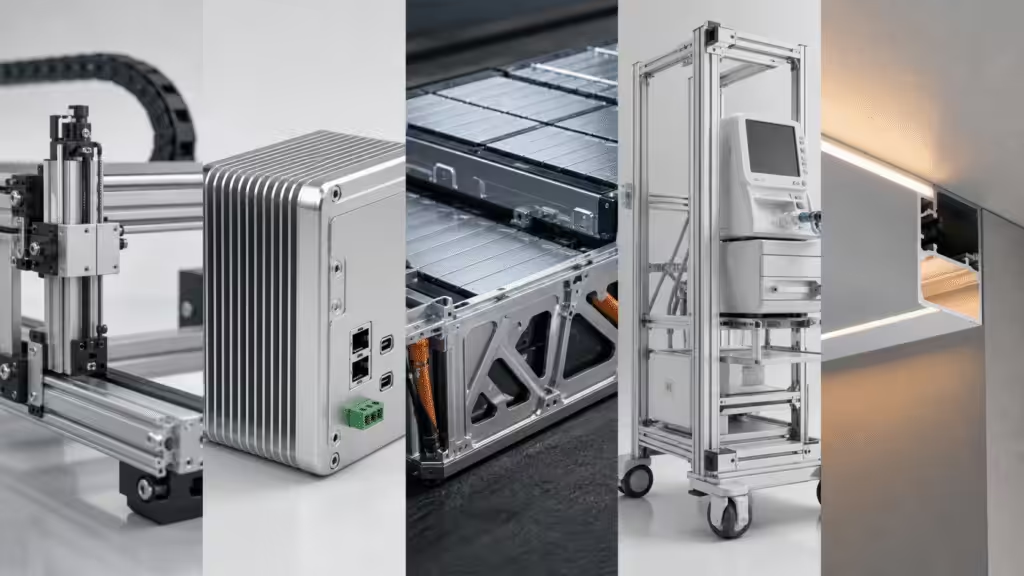
Common Applications for Custom Aluminum Profiles
Industrial Automation
Custom rails, machine beams, guards, sensor mounts, conveyors, and linear-motion supports can integrate cable paths and alignment features. Precision faces may still need machining.
Electronics and Thermal Management
Enclosures can combine heat-sink fins, PCB rails, connector faces, grounding points, and mounting bosses. For thermal products, airflow, fin geometry, base thickness, and interface flatness must be validated together.
Transportation and Electric Vehicles
Profiles can support battery enclosures, structural rails, interior systems, and lightweight subassemblies. These applications may require crash, fatigue, corrosion, sealing, and traceability controls.
Medical and Laboratory Equipment
Custom sections suit equipment frames, covers, rails, and instrument housings. Cleanability, finish, grounding, sharp-edge control, and documentation often matter as much as static strength.
Lighting and Architectural Systems
Profiles can combine LED channels, diffuser tracks, thermal paths, mounting details, and visible surfaces. Finish consistency and fit across long lengths become major acceptance points.
The process should follow the risk. A machine rail, battery enclosure, heat sink, and decorative trim may use the same alloy family, but they should not share one generic inspection plan.
How to Reduce Custom Aluminum Profile Cost
The lowest material price does not guarantee the lowest finished-part cost. Compare the complete route.
Simplify the Cross-Section
Balance walls, reduce deep narrow channels, avoid unnecessary hollows, and use practical radii. Keep features that remove real parts or operations.
Put Precision Where It Pays
Use extrusion tolerances for general geometry. Machine only critical datums and interfaces. Relax dimensions that do not affect fit or performance.
Remove Secondary Operations
An integrated groove, boss, rail, or cable path can replace drilling, brackets, fasteners, and assembly labor. This is where custom extrusion often earns its die.
Freeze the Design Before Tooling
Prototype uncertain interfaces first. A tool correction may be manageable, but repeated revisions consume lead time and confidence.
Plan Volume and Lengths
Share annual demand, release quantities, cut lengths, scrap assumptions, and packaging limits. The supplier needs these inputs to choose the press, billet, cavity count, run plan, and stock strategy.
Choose the Right Process for Each Feature
Not every feature belongs in the extrusion. Our project records include a thermal module where DFM changed a cover from die casting to stamping to reduce cost. The lesson is broader than that part: process loyalty is expensive. Use extrusion, machining, stamping, casting, or assembly where each is strongest.
Ask suppliers to separate die, trial, material, extrusion, heat treatment, cutting, machining, finish, inspection, packaging, and freight. Comparable cost needs comparable scope.
What to Include in a Custom Aluminum Profile RFQ
A complete RFQ helps suppliers quote the same product instead of ten creative interpretations.
Include:
A controlled 2D drawing with revision
A 3D model in a usable format
Alloy, temper, and governing material standard
Critical dimensions, datums, and GD&T
Straightness, twist, flatness, and cut-length requirements
Finished-state dimensions
Surface finish, color, texture, and cosmetic faces
Machining, bending, joining, cleaning, and assembly requirements
Mating parts or interface models
Functional and environmental test requirements
Prototype quantity and first-article expectations
Annual volume, release quantity, and program life
Packaging, labeling, traceability, and shipping length
Target schedule and approval gates
Tool ownership and change-notification requirements
Also state the end use. Suppliers make better DFM decisions when they know whether a groove holds a gasket, a panel, a cable, or someone’s optimism.
Ask the quotation to list assumptions and exclusions. A low price built on mill finish, loose length tolerance, no inspection report, and bulk metal-on-metal packaging is not directly comparable with a finished precision component.
How to Choose a Custom Aluminum Profile Manufacturer
Choose the supplier whose verified process matches your geometry, tolerance, finish, volume, and risk.
Ask for evidence in five areas:
DFM: Can its engineer explain metal-flow, die, tolerance, and downstream risks?
Similar work: Has it produced profiles with comparable size, hollows, walls, finish, and machining?
Measurement: Can it inspect the long profile and the finished features with defined methods?
Production control: Are material, die, process, finish, and revision records traceable?
Response: Does it have a clear plan for trial corrections, nonconformance, change control, and schedule recovery?
Visit or audit the actual production route when the project risk justifies it. Some suppliers extrude in one site, machine in another, and outsource finishing. That can work well, but the quality plan should show every handoff.
Alt: Engineers auditing aluminum profile samples and manufacturing process records.
Frequently Asked Questions
What is the difference between a custom aluminum profile and a standard extrusion?
A standard extrusion uses an existing catalog shape and needs no dedicated profile die. A custom aluminum profile uses tooling made for your cross-section. Custom tooling can integrate functions and reduce downstream work when the design and volume justify it.
Is 6061 or 6063 better for custom aluminum profiles?
6063 often suits complex sections, visible surfaces, anodizing, enclosures, and heat sinks. 6061 often suits higher structural demand, machining, or welding. The correct choice depends on geometry, temper, required properties, finish, and supplier capability.
What tolerances can custom aluminum extrusions hold?
The answer depends on profile size, wall thickness, alloy, die type, feature location, length, and measurement method. Use the governing extrusion standard as a baseline. Machine critical local features when the functional tolerance is tighter than the extrusion process can reliably hold.
Do custom aluminum profiles always need CNC machining?
No. A well-designed cross-section can eliminate much of the machining. CNC is useful for local holes, pockets, threads, end details, and precision datums that do not run continuously along the profile.
How should I prototype a custom profile before paying for a die?
Machine an early section from plate or stock to test interfaces and assembly. You can also modify a standard extrusion for functional prototypes. After the geometry stabilizes, build the extrusion die and validate actual trial material before production.
What should a first-article report include?
It should cover material identity, cross-section dimensions, length, straightness, twist, flatness, machined features, finish, functional fit, cosmetic limits, packaging, process route, and drawing revision. Add application-specific tests based on failure risk.
How do finishes affect aluminum profile dimensions?
Anodizing grows an oxide layer at the surface, while powder coating adds a thicker film. Both can change tight openings, threads, sliders, snap fits, grounding points, and adhesive areas. Define whether dimensions apply before or after finish.
Who should own the custom extrusion die?
The purchase agreement should state ownership, storage, allowed use, maintenance, replacement, inactivity rules, and transfer rights. Do not assume that paying a tooling charge automatically answers each of those questions.
Build the Process Before You Build the Tool
A successful custom aluminum profile starts with a clear function and ends with a controlled production process. The die is important, but it sits in the middle of the story.
Define the interfaces. Design for metal flow. Select the alloy and temper from real requirements. Put tight tolerances on functional features. Validate the finished first article. Then connect every production lot to material, tooling, process, finish, and inspection records.
That approach creates a profile that is light, efficient, and repeatable. More importantly, it creates a part that still fits when production reaches batch ten and the original sample has become office decor.
Our documented manufacturing capabilities span extruded and machined thermal parts, simulation, prototype testing, multiple joining processes, environmental validation, barcode traceability, and MES-supported production control. A useful review starts with your drawing, application, mating parts, annual volume, finish, and critical acceptance criteria.
Tiger.Lei
I'm the founder of Hongjitc. With over 15 years of experience in manufacturing heatsinks, liquid cold plates, and aluminum thermal products, we are here to help. Have questions? Reach out to us, and we will provide you with a perfect solution.