

Direct-to-chip cooling removes heat through cold plates mounted on processors or other heat-generating components. Heat passes through the component interface into the plate, then into coolant flowing inside it. In a conventional sealed design, liquid stays within the cooling hardware.
For a server OEM or system integrator, selecting a cold plate means matching that heat-transfer path to the actual board, coolant supply and mechanical assembly. A power rating alone cannot establish whether the processor will meet its temperature limit.
This guide explains the design requirements that make a cold plate specification useful: the heat map, allowable temperatures, internal geometry, flow and pressure, thermal interface, manufacturing route and validation evidence. It ends with an RFQ checklist for a custom component or assembly.
How Direct-to-Chip Cooling Works
A conventional cold plate contains a fluid passage separated from the electronics by a solid wall. The contact face receives heat from the package through a thermal interface material, or TIM. Internal surfaces transfer the heat into the moving coolant, which carries it to downstream cooling equipment.
For a lidded processor, the local route is:
Silicon → package lid → TIM → cold-plate base → coolant.
The package contains additional internal interfaces. A direct-die assembly changes this stack and needs its own approved contact and mounting requirements; the term “direct-to-chip” does not by itself mean exposed silicon touches the coolant.
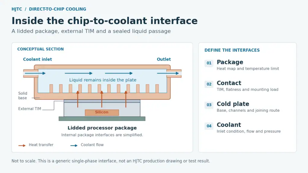
The figure shows a representative single-phase design: the coolant remains liquid while collecting heat. Other direct-to-chip technologies can use phase change, with different fluid and operating requirements.
Define the component and assembly boundaries
A cold plate is one component. A server cooling assembly can also include tubing, couplings, brackets and distribution hardware. CoolIT’s cold-plate loop overview illustrates how that assembly follows the server board layout.
State whether the request covers a bare plate, a plate with mounting hardware, or an integrated loop. Also identify which memory, power or networking components retain air cooling. This keeps the cold-plate scope consistent with the rest of the server.
For a component starting point, review HJTC’s liquid cold plates alongside the requirements below.
Heat Map and Allowable Temperatures
Start server cold plate design with a drawing of the heat sources. Mark contact dimensions, locations, component heights and the power assigned to each source. Where available, include hotspot information and the workload that produced it.
Two packages with equal total power can impose different requirements if their footprints or power distributions differ. Similarly, an assembly spanning several devices must accommodate their individual heights and limits. A single total-watt figure hides these details.
Request the package or platform documentation early. Record which requirements are fixed by the OEM and which can be negotiated during the thermal design.
Name the temperature measurement point
| Temperature | What it describes | What to specify |
|---|---|---|
| Junction temperature | Temperature within the semiconductor | Applicable device limit and approved sensing or estimation method |
| Case or lid temperature | A defined point on the package exterior | Location, allowable value and workload |
| Cold-plate contact temperature | A point on the plate’s mating surface | Sensor position and whether the TIM is included in the comparison |
| Coolant inlet temperature | Fluid entering the cold plate or defined assembly | Measurement location and expected operating range |
| Coolant outlet temperature | Fluid leaving that same boundary | Measurement location and acceptance condition, if required |
A “maximum temperature” without a location is not a usable acceptance criterion. The same applies to thermal resistance: establish the two temperature points before comparing values.
For an explicitly defined case-to-inlet budget:
Rcase-to-inlet, allowable = (Tcase, limit − Tinlet, design) / Q
Here, Q is the heat assigned to the specified cooling path. The result is in K/W or °C/W. This is a screening budget that includes the external case-to-plate interface; it is not automatically the bare cold plate’s resistance. Establish a separate margin and use a suitable model when several sources interact.
Eaton’s cold plate selection guidance uses heat load, coolant conditions and a stated surface-temperature limit to frame selection. It also distinguishes local-fluid and surface temperatures. Preserve the supplier’s definitions when comparing a curve with your budget.
For transient workloads, add the duration and repetition of the load change. A steady-state temperature result cannot describe every short-duration hotspot or control response.
Material, Channel and Base Design
The plate material, base and internal passages work together. Choose them against a common set of thermal, hydraulic and mechanical conditions.
Select materials for the complete fluid path
Copper and aluminum are both used in cold plates. Their suitability depends on the required heat transfer, mass, manufacturing route and compatibility with the coolant and other wetted materials.
Include the plate, internal inserts, joining materials, surface treatments, fittings and seals in the compatibility review. “Water cooling” is not a complete fluid specification: record the coolant product or chemistry, concentration and approved operating range.
Eaton’s liquid-loop corrosion guidance explains how fluid chemistry and material combinations can affect deposits, flow and leakage. Use the coolant supplier’s compatibility requirements for the selected assembly instead of assuming one metal choice resolves every issue.
Treat the internal geometry as a tradeoff
| Design choice | Engineering question | Evidence to request |
|---|---|---|
| Base thickness | How does the base balance heat spreading, conduction distance and stiffness? | Thermal and structural review with the actual contact footprint |
| Fins, channels or inserts | Does the available internal surface transfer enough heat within the pressure-drop budget? | Thermal and hydraulic results for the proposed geometry |
| Inlet and outlet arrangement | Will coolant reach the intended regions, and can the connections fit in the server? | Flow distribution review and an assembly drawing |
| Plate footprint and contact features | Does the plate serve the real heat-source locations and heights? | A common board, package and cold-plate coordinate system |
Boyd’s cold-plate construction datasheet documents several approaches, including tube-in-plate, brazed structures and microchannels. These are manufacturing options, not a ranking that makes the smallest channels suitable for every server.
Ask the supplier to explain what changes when a proposed channel or base dimension changes. A useful design review connects that change to temperature, pressure drop, structural behavior and production requirements. A detailed rendering alone does not answer those questions.
Flow Rate and Pressure Drop
Specify a flow rate together with an allowable pressure drop and the fluid conditions at which both apply. A plate may meet a temperature target at a flow the installed loop cannot deliver.
Keep three quantities separate:
- Flow rate: how much coolant passes through the stated component or branch per unit time.
- Pressure drop: the pressure difference required across a defined flow path at that operating point.
- Operating pressure: the pressure the assembly experiences in service; this is a structural and sealing condition as well as a system parameter.
If a quotation gives a pressure-drop value, ask whether it covers the plate alone or includes hoses, couplings and other connections. Otherwise, two suppliers may be describing different assemblies.
Read thermal and hydraulic results together
A useful performance submission shows both temperature or thermal resistance versus flow and pressure drop versus flow. Boyd’s CPU/GPU cold-plate datasheet provides an example of these paired performance plots. Its product values apply to those products, not to a new custom plate.
Request the coolant, concentration, temperature, heat-source footprint and mounting conditions behind the proposed curves. Identify which values are measured and which are predictions.
Also state the branch arrangement. With plates in series, upstream heating changes the downstream inlet condition. In parallel branches, total loop flow does not establish the flow through every plate. Distribution needs to be checked against branch resistance.
The OCP OAI system liquid-cooling guidelines discuss this balance between preheating, flow distribution and cold-plate geometry. Their platform examples provide context, rather than universal flow or mounting specifications.
Before accepting a design, agree on the lowest expected available flow and the highest design inlet temperature at its connection. These are more useful checks than a single favorable operating point.
TIM, Flatness and Mounting Load
An effective liquid passage still needs a controlled interface with the package. The external TIM fills surface irregularities and helps heat cross the joint. Its installed thickness and contact conditions matter alongside its material properties.
Boyd’s TIM overview explains the role of filling microscopic gaps. Its interface material guide also describes how bond-line thickness and mounting force affect grease interfaces.
For a design review, put these requirements on the same interface drawing:
- Contact area and surface condition. Identify the mating footprint, finish, surface treatment and relevant datums.
- Flatness and tolerance stack. Account for the plate and package surfaces, component heights and the assembled position.
- TIM arrangement. Specify the selected material, application area, installed thickness or compression condition, and rework procedure.
- Load and support. Use the platform’s approved limits and define how brackets, springs or other hardware apply the load.
- Assembly sequence. Establish fastener sequence and any process controls needed to reproduce the intended contact.
Do not treat a tightening torque as a measured contact pressure without an established relationship for the actual hardware. More force may change the plate, package or board deformation, so it must remain within the approved mechanical design.
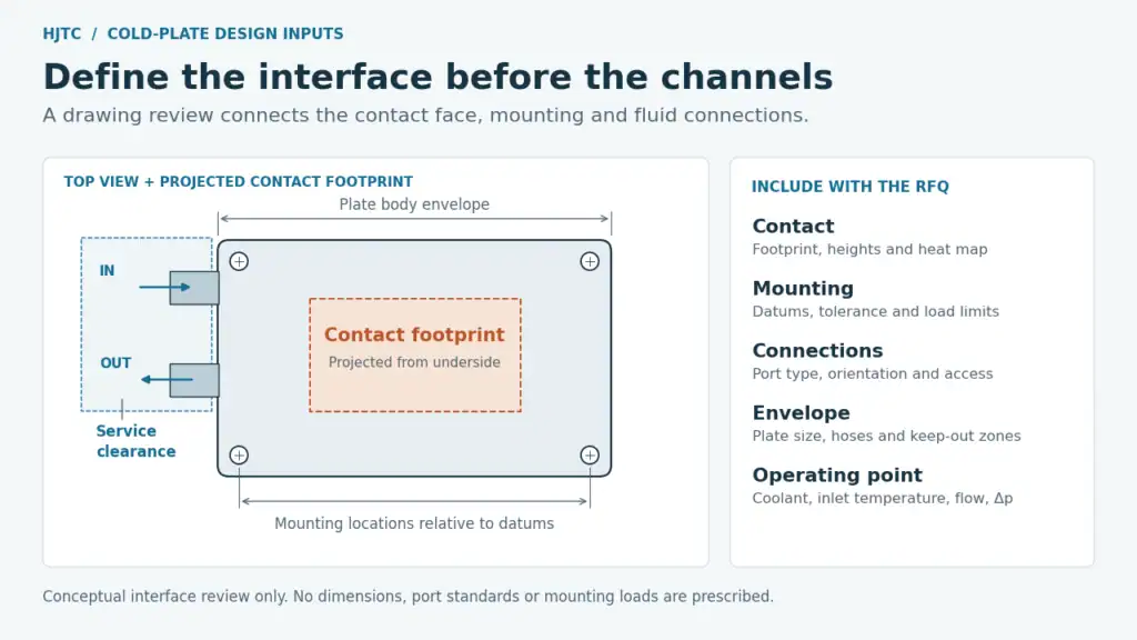
The drawing package should also include the volume needed to install and disconnect fittings. A port can fit in a CAD envelope while leaving insufficient room for a hose bend, tool or service operation.
Eaton’s liquid-loop design guidance includes connections and service access in the design discussion. Assign responsibility for those interfaces before releasing the cold-plate drawing.
Joining, Leak Validation and DFM
The manufacturing route must produce the intended internal passages, contact surface and pressure boundary. Design for manufacturability (DFM) should begin while those features can still be changed.
Brazing and welding are possible joining routes, with different material and geometry requirements. Eaton’s metal fabrication overview describes brazing and friction stir welding for thermal assemblies. A process name alone does not establish the performance of a finished part.
What HJTC’s reference structure tells a designer
HJTC’s server-cooling reference material shows a brazed copper cold-plate assembly connected with tubing. Its broader product brief includes liquid cold plates for high-power chips and high-performance computing.
That reference is useful for an interface review: identify the contact surfaces, joining locations, tube connections, supports and space required around the assembly. It does not supply a verified flow-pressure curve or a complete thermal test record for a new project.
For a similar request, provide the board layout and connection constraints with the thermal requirements. The actual alloy, channel dimensions, joining procedure and validation plan must be established for the proposed part.
Separate the questions answered by each test
| Evaluation | Main question | What the report should identify |
|---|---|---|
| Dimensional inspection | Does the finished assembly meet the interface drawing? | Drawing revision, datums, critical dimensions and results |
| Leak test | Is leakage below the agreed limit under the test conditions? | Medium, pressure, stabilization and test duration, method sensitivity and acceptance limit |
| Pressure qualification | Does the assembly meet the specified structural pressure requirement? | Test objective, loading conditions, method and acceptance criteria |
| Thermal and hydraulic validation | Does the design meet temperature and pressure-drop targets together? | Heat map, fluid conditions, flow, measurement points, mounting setup and measured results |
A CFD result is a prediction. A leak-test pass does not establish thermal capacity, and a thermal result does not qualify the pressure boundary. Match each claimed result to the report that supports it.
Review final flatness after joining and finishing, cleanliness of the fluid passages, connection tolerances and the inspection sequence. Agree which characteristics need a report with the shipment and which require qualification evidence before production release.
CoolIT’s cold-plate engineering discussion likewise treats manufacturability, tolerances, thermal performance and hydraulics as connected design tasks.
The OCP cold-plate workstream lists several requirement documents and revisions. Select the version applicable to the project with the system owner; historical examples should not become universal test-pressure or mounting limits.
RFQ Input Checklist
A useful request for quotation lets each supplier assess the same operating conditions and deliverable. Complete the following fields before comparing proposals. If an input is unknown, identify who will resolve it and what assumption is allowed for the preliminary review.
| RFQ field | Information to provide |
|---|---|
| Supply scope | Bare plate, mounted plate, or integrated tubing/connection assembly |
| Platform and application | Server or module identification and relevant OEM requirements |
| Heat-source map | Locations, contact sizes, heights, power by source and workload profile |
| Temperature acceptance | Junction, case or other defined limit; measurement location and design margin |
| Coolant | Product or chemistry, concentration, material-compatibility requirements and operating range |
| Inlet condition | Minimum and maximum temperature at the specified assembly connection |
| Hydraulic budget | Required branch flow, allowable pressure drop and measurement boundary |
| Pressure conditions | Operating range and applicable qualification requirements, including relevant transients |
| Mechanical package | STEP and dimensioned drawing if available; envelope, datums, keep-out zones and weight constraints |
| Contact and mounting | Surface requirements, TIM arrangement, approved load, supports and assembly method |
| Fluid connections | Port specification, position, orientation, connector requirements and service clearance |
| Validation deliverables | Thermal/hydraulic data, leak-test requirements and dimensional records to be supplied |
| Production needs | Prototype quantity, anticipated production quantity, drawing revision and traceability needs |
| Service conditions | Replacement approach, shipping condition and relevant storage or handling requirements |
What to look for in the supplier’s response
Ask for a proposed construction, an interface drawing and a list of assumptions. The response should connect the selected geometry to your thermal and hydraulic targets, explain the manufacturing route, and identify the validation still required.
Keep unresolved inputs visible through quotation and prototype review. For example, a preliminary quote based on an assumed coolant or mounting arrangement should be updated when that input changes. This makes the comparison between suppliers and revisions much more useful.
Can an existing cold plate be adapted?
Possibly, if its footprint, mounting, fluid connections and performance under your conditions fit the project. Confirm which changes require a new drawing, analysis or validation; a similar external shape is insufficient evidence of compatibility.
Does direct-to-chip liquid cooling remove the need for server airflow?
Check the actual components included in the liquid path. If other devices remain air-cooled, the server still needs an appropriate air path. Cold-plate coverage and total server heat capture are different specifications.
What if the flow rate or allowable pressure drop is not available yet?
Send the known requirements and flag the missing values. They can be treated as open interface questions during the initial review, but should be agreed before thermal performance and system compatibility are accepted.
Preparing a custom cold plate or server cooling assembly? Request a Cold Plate Design Review. Share your heat map, temperature limit, coolant conditions and mechanical drawing to start a focused discussion with HJTC.