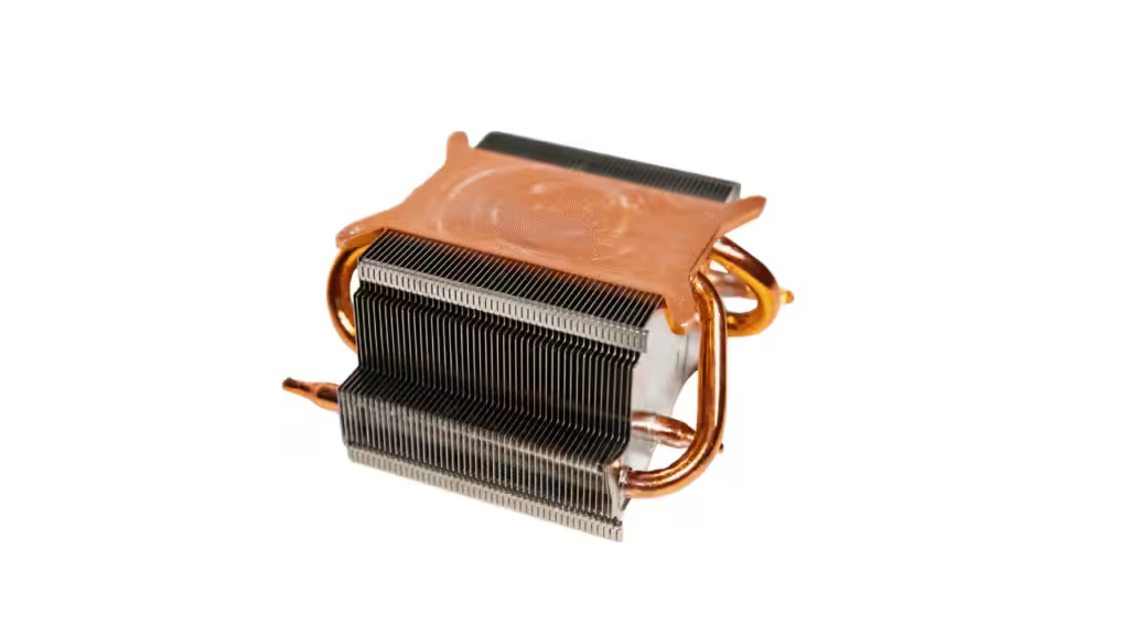
A heat pipe heat sink can move heat from a crowded component area to a fin stack with more room to reject it. However, adding heat pipes does not automatically solve a cooling problem. The assembly still needs an effective heat collection surface, reliable thermal joints and enough airflow through the fins.
Heat pipe heat sink design should begin with the complete heat route: source, collector, heat pipes, condenser and fin stack. Define the operating conditions and temperature limits before choosing pipe count or comparing layouts. For OEM electronics, the useful outcome is an assembly that fits, meets its temperature target and can be built consistently.
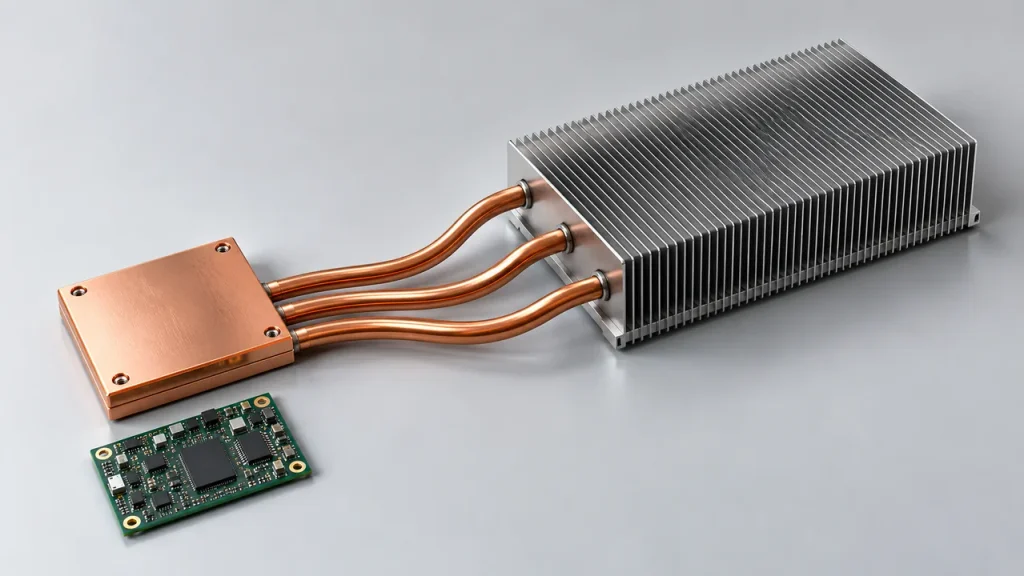
When a Heat Pipe Heat Sink Is a Useful Starting Point
A heat pipe contains a working fluid inside a sealed enclosure. Heat evaporates fluid near the source; vapor travels to a cooler region, condenses and releases heat. A wick can return liquid toward the heated region. The resulting assembly transports heat, while its fins and surrounding air provide the final rejection path. Radian’s heat pipe overview explains this operating principle.
Consider this approach when the available fin area is separated from the component, or when a localized source needs to distribute heat across a larger sink. A remote fin stack can also help when component height restrictions leave little space directly above the source.
First establish a simpler baseline. If a conventional aluminum sink can meet the requirement within the available space and airflow, extra joints and formed pipes may add unnecessary complexity. HJTC’s extruded heat sink selection guide provides a starting point for that comparison. For a broader architecture decision involving vapor chambers or liquid cooling, see the high heat flux cooling guide.
Define the Heat Route Before Choosing Pipe Count
Create a layout that identifies each heat source, its contact footprint and its position relative to the mounting datums. For multiple components, show which loads operate simultaneously. A combined wattage alone does not describe how heat enters the collector.
Next, mark the permitted pipe route and the volume available for the condenser and fins. Include connectors, fasteners, service access and enclosure features that could interfere with assembly. Record the actual installation orientation, including any orientations used during normal operation.
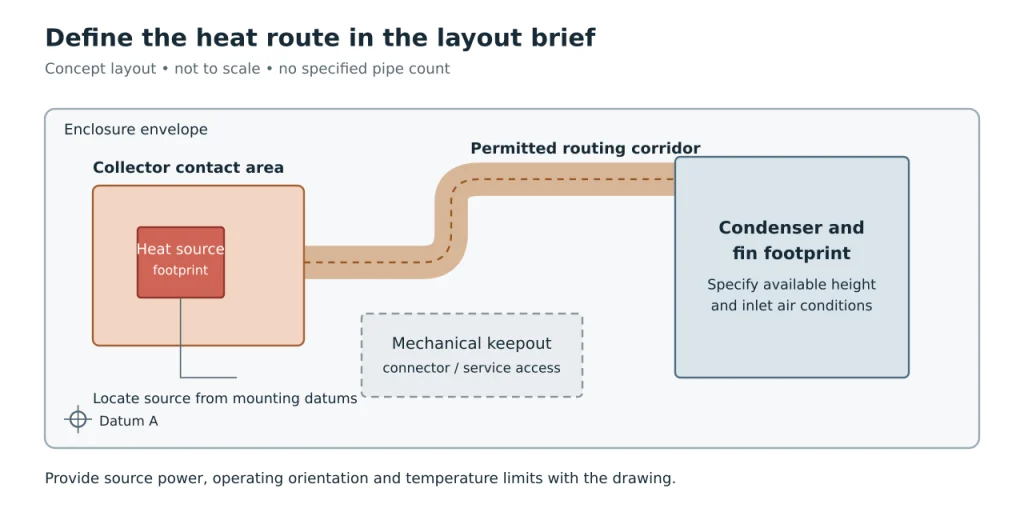
Set the temperature budget using clearly named measurement points. For example, assume a hypothetical assembly must transfer 120 W, its inlet air is 40°C and its collector reference point must remain at or below 70°C. The allowable collector-to-inlet thermal resistance is:
R = (70 − 40) / 120 = 0.25 K/W
This example assumes the full 120 W passes through the assembly. It is not an HJTC performance specification, and it is not a junction-to-ambient limit. If the requirement starts at semiconductor junction temperature, account for the relevant package and interface temperature drops using an appropriate device thermal model. A collector measurement cannot be substituted for a junction measurement without that connection.
Compare Heat Pipe Integration Layouts
Two decisions are often mixed together: how the source couples to the heat pipes, and where the fins sit. Embedded and direct contact arrangements describe the source interface. A remote fin stack describes the rejection location and can use either interface concept.
| Arrangement | What it changes | What to verify |
|---|---|---|
| Heat pipes embedded in a collector | A plate collects and spreads heat before transferring it into the pipes. | Source coverage, collector thickness, groove fit and joint continuity. |
| Direct contact heat pipe surface | Formed pipe surfaces contribute directly to the component contact face. | Coplanarity, gaps, contact coverage, mounting pressure and remaining pipe integrity. |
| Remote fin stack | Pipes connect the source region to a separate rejection region. | Routing envelope, orientation, condenser contact and installed airflow. |
Removing a solid layer can shorten part of the conduction path, but it does not guarantee lower total resistance. A well-integrated collector may distribute heat more effectively than a poorly finished direct contact surface. Celsia’s assembly comparison illustrates why interface layout deserves attention alongside the heat pipe itself.
Compare candidate assemblies using the same source footprints, heat loads, inlet temperature, installation orientation and temperature endpoints. Also keep the enclosure and fan operating constraints consistent. Different fin stacks can change airflow at the same fan setting, so equal fan model or speed does not establish equal flow. Record those differences instead of attributing every temperature change to the pipes.
Control the Interfaces Along the Heat Route
Source to Collector and Heat Pipes
The source contact face needs a defined flatness requirement, mounting arrangement and thermal interface material. Specify where clamping force enters the structure and how the component is protected from excessive loading. Check the assembled condition: a flat loose plate can distort when mounted.
Do not assume each pipe receives an equal share of total power. A small, offset source may feed nearby pipes more strongly than distant ones. Ask the supplier to evaluate heat collection across the actual footprint before accepting a design based only on total pipe count.
Heat Pipes to the Fin Stack
Treat the condenser joint as a controlled feature on the drawing. Define the intended contact region, joining method, compatible surface finishes and inspection requirements. A pipe passing through a fin stack is not proof of a consistent thermal bond.
Soldering, adhesive bonding and mechanical attachment require different process controls; they should not be ranked without the materials and service conditions. MyHeatSinks discusses these options in its heat pipe heat sink guidance. For a quotation, request the proposed joint construction and the evidence that will verify it on samples.
Separate mechanical support from thermal contact wherever the design requires it. Identify the features that locate the collector, retain the fin stack and carry handling or vibration loads. Avoid leaving a supplier to infer those functions from a thermal illustration.
Check Capacity in the Final Formed Geometry
A pipe’s usable transport capacity depends on more than its outside diameter. Wick construction, operating temperature, orientation, effective length and the geometry of the heated and cooled regions all matter. Bending and flattening can change performance, so data for a straight round pipe may not represent the supplied part. Celsia’s heat pipe design guide covers these dependencies.
Request capacity information for the proposed formed geometry and operating conditions. State the coldest and hottest expected environments and the least favorable operating orientation. Confirm how startup, continuous load and short load peaks will be assessed. Do not adopt a universal watts-per-pipe value or bend radius from an unrelated product.
At assembly level, ask whether the highest-loaded pipe has sufficient margin. Increasing pipe count is useful only if the collector can feed the added pipes and the condenser can release their heat. The supplier’s explanation should connect those conditions to the proposed layout.
Match the Fin Stack to Installed Airflow
Once heat reaches the condenser, it still needs a suitable path into the surrounding air. Specify the intended fan, inlet restrictions, exhaust location and any duct or shroud that controls flow through the fins. A larger remote fin stack may create packaging opportunities, but its location can also expose it to warmer inlet air or recirculation.
Keep the quoted airflow condition visible in every performance comparison. ATS notes that ducted test results can misrepresent an application where air bypasses the fins. Its heat sink testing discussion also identifies heat loss through the test board as a source of error when calculating thermal resistance.
Use the final enclosure arrangement for the acceptance test, or document precisely how a fixture represents it. A bench result is useful only when its boundary conditions are understood.
Use Models to Select Layouts and Prototypes to Verify Them
A thermal model can help compare collector geometry, source positions and condenser locations before tooling decisions. Document how the model represents heat pipe transport and joint resistance. A single optimistic conductivity value can hide the very interfaces the study needs to examine.
Use initial sample measurements to check those assumptions. MyHeatSinks describes adjusting a heat pipe model against prototype results; this is a practical reason to preserve measurement locations between simulation and testing.
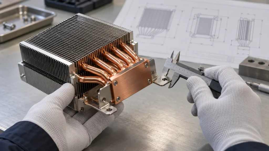
Before a sample is built, agree on three groups of acceptance criteria:
- Thermal: defined load cases, inlet air temperature, orientation, temperature measurement points, stabilization rule and allowable temperatures. Record how heat escaping through other paths is handled.
- Mechanical: contact-face condition, mounting datums, permitted distortion, routing clearance and installation access. Verify fit in the intended enclosure.
- Production: drawing revision, approved materials and joint construction, inspection records and change notification. Agree which characteristics require routine inspection and which require qualification testing.
For troubleshooting, compare temperatures at the collector, accessible pipe regions and fin base under the same load. These observations can guide further checks, but they do not individually prove a wick failure or a defective joint. Confirm the explanation with targeted measurements before changing the design.
Prepare a Heat Pipe Design Brief for HJTC
HJTC’s heat sink range includes heat pipe, extruded, skived fin and bonded fin options. A useful sourcing request should let those alternatives be assessed against the same project requirements, with supplier-specific capabilities and validation responsibilities confirmed during the quotation process.
| Information to supply | Decision it supports |
|---|---|
| Source map with power by component and simultaneous load cases | Collector coverage and heat distribution into the pipes. |
| 2D and 3D enclosure data, mounting datums and keepout zones | Source interface, pipe route, fin position and assembly access. |
| Ambient range, inlet air conditions, fan details and operating orientations | Transport-capacity review and realistic rejection conditions. |
| Named temperature limits, measurement points and acceptance procedure | A quotation and prototype result that can be compared consistently. |
| Prototype quantity, forecast volume, target schedule and required records | Sourcing approach, sample planning and production documentation. |
Separate fixed constraints from negotiable ones. For example, identify whether a mounting pattern is frozen while the fin stack location can still move. This helps avoid optimizing a layout that cannot be installed.
Contact HJTC with the source map, available envelope and operating conditions to start a heat pipe heat sink sourcing discussion. Ask for the proposed assembly construction, sample scope and validation plan alongside the quotation.
Frequently Asked Questions
How many heat pipes does an OEM heat sink need
There is no reliable count based on total watts alone. The answer depends on the load entering each pipe, its formed geometry and operating conditions, and the condenser’s ability to release heat. Request a layout-specific assessment.
Is direct contact always better than an embedded design
No. Direct contact changes the source interface, but contact quality and heat distribution still matter. Compare the complete assemblies under consistent boundary conditions, including their actual mounting and interface materials.
Can a heat pipe heat sink operate without a fan
It can be designed for natural convection when the available surfaces and environment can reject the required heat. The heat pipes do not create airflow. Verify the complete passive assembly in its intended orientation and enclosure.