A fan can move plenty of air through an enclosure while too little reaches the heat sink channels. Heat sink airflow bypass occurs when cooling air takes an easier route above or beside the fins. A shroud can redirect that flow, but its added resistance also changes the load on the fan. The useful result is a lower component temperature under the intended operating conditions.
This guide covers forced-air, parallel-fin assemblies inside electronics enclosures. It explains how to identify bypass, separate it from hot-air recirculation, and evaluate a duct change before specifying a different heat sink.
Identify Where the Air Goes
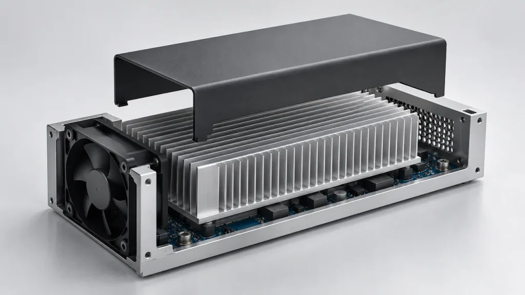
Start with a section through the assembled enclosure. Include the lid, circuit board, cables, adjacent components, and the fan mounting opening. Inspect the complete route from intake to exhaust, with the product in its normal closed configuration.
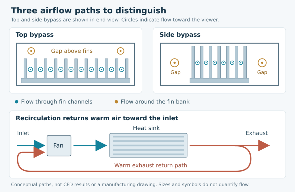
There are three different flow problems to distinguish:
- Top bypass: air travels through the clearance above the fin tips.
- Side bypass: air follows an open corridor beside the fin bank.
- Recirculation: some heated discharge air returns toward the cooling inlet.
Eaton’s ducting overview distinguishes top and side bypass and shows how an enclosing duct directs flow into the fin passages. A nearby wall or board may already provide part of that boundary.
Recirculation needs a separate check. Closing a side gap does not establish where the exhaust goes. Also inspect the separation between intake and outlet. Air heated by an upstream component can raise the heat sink inlet temperature even without a recirculation loop.
Separate Fan Airflow from Flow Through the Fins
At the heat sink, the approaching flow divides between the fin passages and the surrounding openings. A reading at the enclosure outlet combines these routes. It cannot, by itself, tell you how much air crossed the fin field.
Robert E. Simons’ parallel-fin bypass analysis treats the duct flow and the flow through the heat sink separately. This distinction explains why a design can have substantial enclosure ventilation and still cool a particular device poorly.
It also prevents a misleading target: maximizing the percentage of air passing through the fins. A high percentage can accompany a small absolute flow. Evaluate the amount of useful flow and the resulting temperatures together.
For a first inspection, look for a large unobstructed opening that connects the upstream and downstream sides of the heat sink. Treat its presence as a reason to investigate, not proof that it dominates the airflow. The channel geometry, surrounding restrictions, and fan behavior determine the actual split.
Check the Conditions Behind Catalog Performance
A thermal resistance curve applies to its stated test arrangement. Before using it to predict an installed temperature, check whether airflow was fully ducted, where velocity was measured, and which air temperature was used as the reference.
For example, Alpha’s selection guide states that its catalog thermal resistance data use fully ducted airflow. It also identifies nearby boards and chassis walls as boundaries that influence bypass. That is a specific manufacturer’s condition; it should not be assumed for every catalog.
Ask for the test duct dimensions and compare them with the assembled enclosure. A nominal velocity measured upstream in a large passage is not automatically the velocity inside the narrower fin channels. Likewise, a room-temperature reading may differ from the air actually entering the heat sink.
If the basic heat sink size has not yet been selected, use HJTC’s extruded heat sink selection guide first. The following steps address the airflow boundary around that candidate.
Design the Shroud Around the Whole Cooling Route
Control the top and side gaps
Use a cover or guide that follows the intended flow direction and limits the easiest routes around the fin bank. For a parallel-channel design, preserve open entrances and exits along those channels. A cover that blocks the discharge can defeat its purpose.
Dimension the shroud from the assembled stack, including lid position and attachment features. Check the largest likely gap after assembly tolerances, as well as the smallest clearance needed to avoid interference. There is no universal millimeter allowance that works for every fin pattern and fan.
Preserve cooling for nearby components
A local shroud changes how the enclosure shares airflow. Identify components that depend on the same stream before closing an open corridor. Keep their temperature limits in the evaluation, especially when the new route sends warmed air downstream.
Avoid placing a duct wall or a bundle of wires directly against the fan inlet or outlet. ATS’s fan-sink experiments demonstrate that neighboring obstructions and system flow can affect local fan performance. The tested geometry matters, so use this as a reason to assess the actual arrangement rather than as a universal loss factor.
Recheck the fan operating point
Adding a shroud changes system resistance. The operating flow follows the interaction between that resistance and the fan’s pressure-flow characteristic. A fan’s free-air rating does not establish its delivery through the revised assembly; Oriental Motor explains this pressure-loss relationship.
Review the intended operating range on the selected fan curve, including the effect of filters and other restrictions. ATS’s fan-curve guidance also discusses unstable operating regions. Do not assume that the tightest duct gives the best overall result.
Run a Controlled Shroud Trial
The following comparison plan isolates changes to airflow routing while keeping the rest of the assembly as consistent as practical.

Establish the baseline
Run the original closed assembly at a defined load and fan setting. Record the heat source operating condition, inlet air temperature, a repeatable heat sink base temperature, and the relevant device temperature. Include nearby components that could lose airflow after the change.
Keep probes in the same positions for each run. Place the inlet air probe clear of heated surfaces and document its location. Allow temperatures to stabilize against a predefined criterion appropriate to the assembly; record the actual waiting period and remaining drift.
Change only the airflow guide
Install a removable trial shroud without disturbing the heat sink mounting or thermal interface. Keep the enclosure panels, cable route, load, and fan control command unchanged. Record fan RPM where available, because a matching control command does not prove identical speed or airflow.
Measure the same temperatures again. If the controller normally changes fan speed with temperature, first make a comparison at a controlled setting, then repeat under the normal control strategy. This separates the duct effect from the controller response.
Repeat and record the comparison
Return to the original configuration when practical. An A-B-A sequence helps reveal drift or an unintended change during assembly. A small temperature difference is inconclusive if it is comparable to instrument uncertainty or run-to-run variation.
| Record in each run | Purpose |
|---|---|
| Load condition and power measurement point | Reveal changes in heat generation |
| Local inlet air temperature | Identify changes in the cooling air supplied |
| Base and device temperatures | Compare both sink behavior and the component outcome |
| Fan command and measured RPM | Expose changes in fan control or speed |
| Neighboring component temperatures | Detect a cooling penalty elsewhere |
| Shroud revision, gap dimensions, and enclosure state | Make the configuration reproducible |
Use temperature differences as comparison evidence. Do not label total electrical input power as heat flowing through the sink without accounting for other paths. ATS’s testing-method discussion explains why heat lost through a board can distort a derived heat sink thermal resistance.
Interpret the Result Before Choosing the Next Change
The observations below guide the next investigation; none establishes a cause on its own.
| Observed change | What to check next |
|---|---|
| Device and base temperatures fall while inlet temperature stays similar | Improved local convection is plausible; verify load, fan behavior, and repeatability |
| Device temperature falls and inlet air becomes cooler | Investigate exhaust return or upstream air heating before attributing the gain entirely to fin flow |
| Base becomes cooler but the device barely changes | Check the interface, sensor location, and device power state |
| Target device improves but a nearby component gets hotter | Revise airflow allocation or give the neighboring device a suitable cooling route |
| Temperatures rise or fan behavior becomes erratic | Inspect added restrictions, fan operating range, and unintended blockage |
When results remain ambiguous, measure local velocity distribution or compare pressure at defined points using suitable equipment. One fast-moving spot does not establish uniform channel flow. Record the measurement plane and method so the next design can be compared on the same basis.
Carry the Successful Configuration into the Design
A useful trial should produce a drawing change and a reproducible assembly description. Specify the shroud attachment, relevant gap limits, inlet and outlet openings, and cable locations. Confirm that normal service access does not leave the guide incorrectly installed.
Repeat the evaluation under the conditions the product must tolerate, such as the specified ambient range, operating load, fan control behavior, and filter condition. Acceptance should cover component temperature limits and the project’s noise and power constraints.
An external example illustrates the scope of this work: ATS’s GaN and SiC power-module case study evaluates duct routing, fan operating point, and thermal interface behavior together using analysis and CFD. It supports assessing the complete assembly. It does not supply a transferable percentage improvement for another product.
Discuss the Airflow Boundary with HJTC
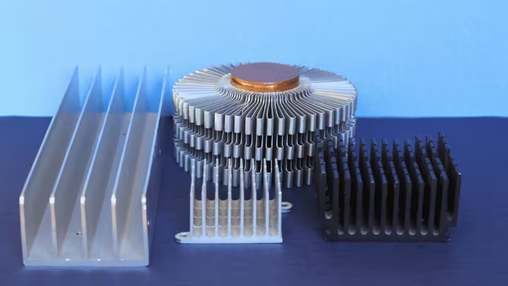
HJTC’s heat sink product range includes extruded, skived-fin, bonded-fin, and heat-pipe configurations. When discussing a candidate, include the enclosure section around the fins and the proposed air route alongside the heat sink drawing.
For a focused inquiry, share the fan model and curve, assembled clearances, load condition, and any baseline-versus-shroud results. Mark which dimensions are fixed and which can change. These details make the sourcing discussion more specific than a request for a larger sink based only on a fan’s rated airflow.
Contact HJTC about your heat sink requirements.
Frequently Asked Questions
Does every heat sink need a duct
No. Some assemblies already have useful flow boundaries formed by their chassis or adjacent boards. Others use cooling arrangements outside this guide’s scope. Evaluate a duct when the existing route leaves insufficient cooling at the target device.
How small should the gap above the fins be
Select the gap for the particular geometry, assembly tolerances, and fan capability. Compare the expected minimum and maximum gaps during development. A clearance copied from another product is not a verified design rule.
Is a push fan better than a pull fan
Neither arrangement is universally better. Fan inlet conditions, outlet restrictions, local flow distribution, and warm-air return all matter. Compare the proposed arrangements in the enclosure at the intended fan control settings.