
The aluminum heat sink manufacturing process determines more than the shape of the fins. It also establishes the material condition, mounting accuracy, surface finish, and repeatability of the finished component.
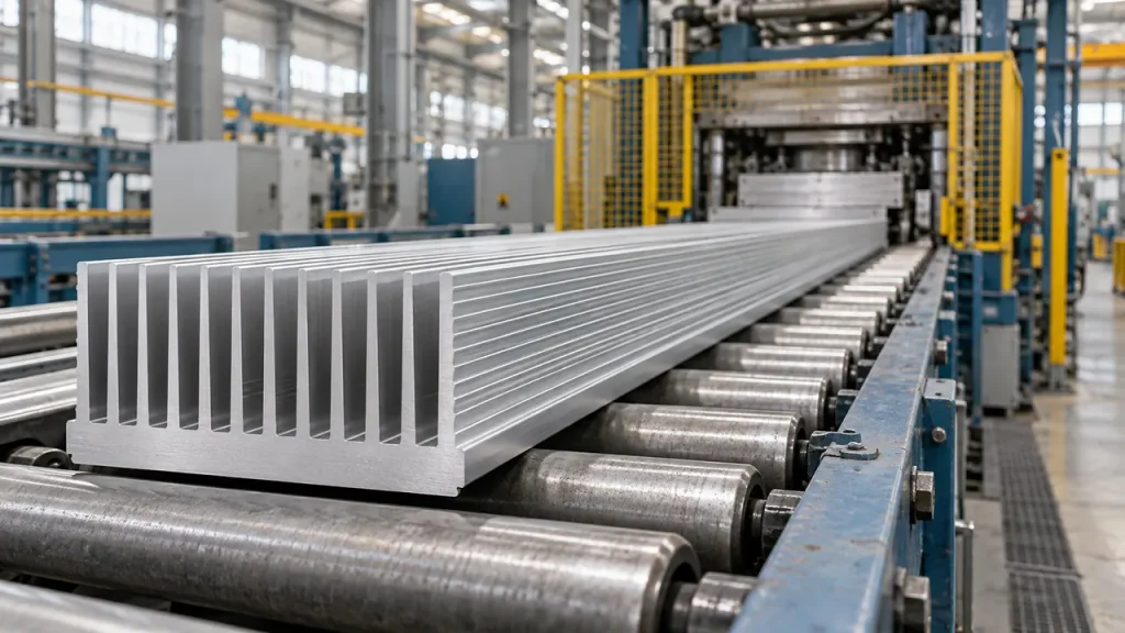
For an extruded heat sink, the route starts with a heated, solid aluminum billet and a profile die. The extrusion then undergoes the specified cooling and heat treatment, followed by cutting, machining, finishing, and inspection. Other heat sinks may be cast, skived, machined from stock, or assembled from separate fins. This guide follows the extrusion route and explains what to confirm at each production stage.
How Is an Aluminum Heat Sink Manufactured?
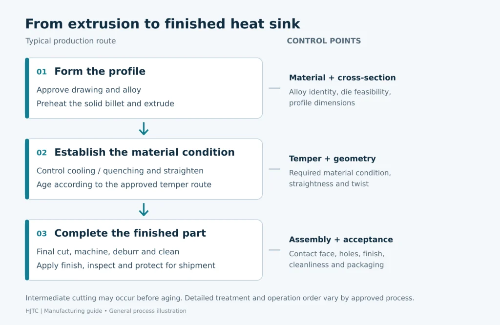
A typical extruded aluminum heat sink passes through six stages: drawing and material approval; billet heating and extrusion; controlled cooling, straightening, and aging; final cutting and machining; surface treatment; and inspection and packaging. The die establishes the continuous cross-section, while secondary operations create features specific to the assembly.
Treat this as a process map, not a universal factory recipe. Rough cutting may occur before aging, and final cutting or machining may occur afterward. The alloy, specified temper, finish, and part geometry determine the approved production sequence.
1. Approve the Drawing, Alloy, and Production Route
Begin with a drawing that distinguishes the extrusion profile from the finished component. A profile drawing defines the cross-section. A finished-part drawing also needs the cut length, hole locations, threads, machined faces, surface requirements, and revision identifier.
6063 is a common starting point for aluminum profiles because it combines good extrudability with a surface that responds well to anodizing. Hydro identifies T5 and T6 among the common tempers for 6063 extrusions. The alloy number alone does not specify the final material condition.
For purchasing, specify the alloy and temper together and identify the documentation required with the order. If a supplier proposes a substitute, have it reviewed against the thermal and mechanical requirements before production. Our heat sink materials guide explains the broader material selection tradeoffs.
Decide which features need special control. A useful drawing review asks:
- Which face contacts the component or thermal interface material?
- Which dimensions locate the heat sink in the enclosure?
- Which areas need machining, masking, or a defined appearance?
- Which measurements must be checked after the final surface treatment?
Example: for a power module bolted to the underside of an extrusion, identify that underside as the thermal contact face. Define its flatness requirement, the mounting-hole pattern, and the surface condition in one drawing revision. This gives the machining and finishing teams a shared reference instead of separate interpretations of “flat base.”
2. Heat the Billet and Extrude the Profile
The billet and tooling are prepared for the selected alloy and process. The billet is heated until it can deform under pressure, but it remains solid. A press forces it through the die opening to create the long profile. Extrusion is therefore different from pouring or injecting molten aluminum into a casting mold.
For a straight-fin heat sink, the die creates the base and longitudinal fins together. Fin channels place demands on the thin sections of the die, so a thermally attractive cross-section still needs a manufacturability review. Eaton’s extrusion overview highlights this tooling constraint.
Ask for that review before freezing the profile. It should address the proposed fin geometry, transitions, extrusion envelope, and any allowance needed for later machining. Avoid treating a generic fin aspect ratio or press tonnage as a guarantee that a particular shape can be produced.
An existing profile can be a useful starting point if its section fits the application. A new die is relevant when the required cross-section cannot be obtained from an available profile. Either way, compare the finished-part quotation: tooling, post-processing, finish, inspection, and order quantity all belong in the comparison.
3. Control Cooling, Straightness, and Temper
After extrusion, cooling and subsequent treatment establish the required material condition. Straightening corrects profile geometry; aging changes material properties. These operations have different purposes and should not be combined into a vague instruction to “harden the heat sink.” The Aluminum Extruders Council distinguishes quenching, straightening, and aging in its process guidance.
T5 and T6 are material temper designations, not thermal performance ratings. T5 describes material cooled from the elevated-temperature shaping operation and then artificially aged. T6 describes material that has undergone solution heat treatment and artificial aging. The designation specifies a condition; it does not, by itself, describe every piece of equipment or handling step used to achieve it.
For a production order, agree on the specified temper and the evidence needed to confirm it. Request straightness and twist checks where they matter to assembly. Do not select an aging temperature or holding time from a general blog and apply it to every alloy and profile.
Also distinguish whole-profile straightness from local contact-face flatness. A long bar may be straight enough to cut and fixture, while the component contact face still requires a separate machining and inspection plan. Put both requirements on the relevant drawing rather than assuming one measurement proves the other.
4. Cut, Machine, Deburr, and Clean
Extruded stock is cut into individual blanks or finished lengths. Application-specific work can then add drilled holes, threads, pockets, mounting features, or a machined contact face. This is the transition from a repeatable profile to a part that fits the assembly.
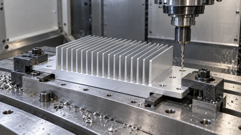
Use the drawing to identify the purpose of each operation. For example, a clearance hole allows a fastener to pass through, while a tapped hole supplies the mating thread. A pocket may provide component clearance; a face-machining operation may establish the contact surface. These features should have their own dimensions and acceptance requirements.
Discuss fixturing during the process review. Ask how the base will be supported and how thin fins will be protected during cutting and machining. When a face is inspected for flatness, define the measurement condition so that fixture pressure does not hide a free-state distortion.
Do not assume that every extruded heat sink needs extensive CNC work. A simple cut-to-length profile may already satisfy the application. Conversely, adding many pockets and setups can change the cost case for extrusion. Review secondary operations together, including tool access and the order in which surfaces become reference features.
Include deburring and cleaning in the acceptance plan. Identify sharp edges, loose chips, blocked channels, and residues that could interfere with assembly. Stamping is a separate manufacturing method for some heat sinks and may suit particular secondary features; it is not a mandatory step for every extrusion or a substitute for specifying a thread-making operation.
5. Specify the Finish and Contact Areas
A finished heat sink may retain an agreed mill finish or receive a surface treatment such as anodizing. The choice should follow the operating environment, appearance requirements, electrical interfaces, and assembly design. An anodized surface is an oxide layer formed on the aluminum; it is not a change to the bulk alloy.
Before placing the order, mark the surfaces that need separate treatment. A useful finishing drawing identifies:
- The required finish and its applicable specification.
- The component contact area and whether it is coated or masked.
- Threads, grounding points, and other functional interfaces.
- Surfaces that need dimensional verification after finishing.
- Cosmetic zones and the agreed visual acceptance conditions.
Avoid instructions such as “black everywhere” if the contact face or an electrical connection has a different requirement. Likewise, do not assume that an attractive sample establishes the coating thickness, surface condition, and fit of every production part.
For thermal approval, evaluate the finished surface in the intended assembly with the specified thermal interface material and mounting method. A coating choice alone does not establish a heat sink’s wattage rating. The heat transfer guide explains why the complete path from component to surrounding air matters.
6. Inspect the Finished Part and Protect It for Shipment
Write the acceptance plan before approving a production sample. Separate dimensional and material checks from thermal qualification: they answer different questions. The following is a suggested buyer–supplier checklist, to be tailored to the drawing and application.
| Check | What to define | Why it matters |
|---|---|---|
| Material and temper | Required identification and supporting records | Confirms the ordered material condition |
| Profile and cut length | Drawing dimensions, straightness, and twist where relevant | Establishes fit within the assembly |
| Contact face | Flatness, surface condition, and measurement setup | Controls the specified mounting interface |
| Holes and threads | Location, size, depth, and inspection method | Supports repeatable installation |
| Fins and cleanliness | Allowed damage, burrs, chips, and residue | Protects handling and assembly quality |
| Finish and masking | Treatment requirements and functional zones | Confirms the final surface matches the order |
Use a production-representative sample for thermal qualification. Record the heat-source footprint and power, inlet air temperature, orientation, airflow arrangement, thermal interface material, and mounting condition. A temperature result without its test conditions is difficult to reproduce or compare.
Keep qualification and routine inspection linked to the same drawing revision. If the alloy, profile, finish, machining route, or assembly interface changes, review whether the existing qualification still represents the delivered part. Agree on lot records and sampling requirements rather than assuming every unit receives the same thermal test.
Packaging belongs in this discussion. Specify protection for fins and contact faces, prevent loose metal parts from rubbing together, and retain part and lot identification. For delicate geometries, request a packaging sample alongside the first finished parts so shipping protection can be assessed before the full order.
When Should You Use a Different Manufacturing Method?
Extrusion is a useful route when the design benefits from a repeated cross-section. It is one option among several. Use the comparison below to frame an engineering discussion, then evaluate a quotation and sample for the actual geometry. Manufacturing method alone does not guarantee better cooling.
| Method | How the shape is made | Main question to resolve |
|---|---|---|
| Extrusion plus secondary work | A die forms a continuous profile; cutting and machining finish it | Can the required section be extruded with manageable post-processing? |
| CNC machining from stock | Material is removed to create the component | Does geometry flexibility justify machining time and material removal? |
| Skiving | Thin layers are cut and raised from a solid base to create fins | Are the fin geometry and handling requirements suitable? |
| Die casting | Molten alloy fills a mold to form an integrated shape | Do alloy choice, tooling, and production quantity fit the project? |
| Bonded or brazed fins | Separate fins are joined to a base | Can the joints and assembly meet the thermal and mechanical requirements? |
For example, a changing three-dimensional shape may require substantial machining after extrusion. A separate-fin construction may offer a different way to achieve the required geometry. Compare complete manufacturing routes rather than the price of an unfinished blank.
What to Send HJTC for a Manufacturing Review
HJTC’s extruded aluminum heat sink range includes AL6063 profiles in compact, standard, high-density, large, and special-profile categories. Start with the relevant product family, then confirm the finished-part requirements for your application.
For an initial discussion, prepare the following:
- A 2D drawing and, if available, a 3D model with matching revisions.
- Alloy and temper requirements, or a request to review the material choice.
- Finished dimensions, contact-face requirements, holes, and threads.
- Finish, masking, assembly hardware, and packaging requirements.
- Prototype quantity, expected production volume, and delivery needs.
- Heat load, heat-source footprint, temperature limits, and airflow conditions.
- Required inspection records and sample approval criteria.
Contact HJTC with this information to discuss profile options and quotation requirements. Confirm the proposed production route and acceptance criteria in the project documentation before ordering.
Frequently Asked Questions
Is aluminum melted to make an extruded heat sink?
No. During extrusion, the billet is heated to a deformable but solid state and pushed through a die. Die casting uses molten metal and follows a different route.
Does every extruded heat sink need CNC machining?
No. Some applications need only an appropriately finished, cut-to-length profile. Holes, threads, pockets, or a controlled contact face can introduce secondary machining requirements. Specify these from the assembly needs rather than assuming every part requires the same operations.
Is T6 always better than T5 for a heat sink?
The temper should match the material and application requirements. T5 and T6 describe processing conditions, not cooling grades. Select the required mechanical properties and verify thermal performance in the finished assembly instead of treating the higher number as a universal improvement.
Can a standard extrusion be customized?
Often, yes. A suitable existing profile can be cut and machined to add mounting features. Changes to the continuous cross-section may require a different profile or new tooling. Confirm both the profile availability and the finished-part requirements.
What should be approved before volume production?
Approve the drawing revision, material and temper, production-representative sample, finish, inspection criteria, and packaging. Record the thermal qualification conditions separately. This creates a concrete reference for comparing subsequent deliveries and reviewing proposed changes.