Design an extruded aluminum heat sink by defining the heat load, temperature limit and available airflow, then selecting a cross-section that can meet those conditions and be manufactured consistently. Review the base, fins, interface and mounting together, and verify the finished assembly before releasing the design for production.
The useful design output is more than a finned CAD model. It is a drawing tied to operating conditions, a thermal target and an agreed test method. This guide takes an electronics or power-module project from those initial requirements to a review with HJTC.
Start with the Operating Conditions and Thermal Target
Write down the heat that the cooling assembly must remove. For a power converter, the electrical output rating is not its heat dissipation. Use the losses at the relevant operating point, with their distribution across the devices being cooled. Record peak duration as well as continuous operation.
Define the temperature reference precisely. A permitted junction temperature, component case temperature and heat sink base temperature represent different points on the heat path. Package-specific thermal data are needed to relate them. A simplified series model is useful when the sink carries the dominant heat flow; substantial PCB or chassis paths require a more complete model.
Include the inlet-air temperature at the heat sink, installation orientation, enclosure dimensions and surrounding obstructions. A room-temperature bench test does not establish performance inside a warm cabinet. See our guide to how a heat sink transfers heat for the underlying mechanisms.
Build a thermal budget with explicit margin
Consider a hypothetical single-module project. The numbers below illustrate the method and are not an HJTC rating or test result. Assume steady operation and that the full 100 W enters the heat sink through the defined case interface.
| Design input | Illustrative value |
|---|---|
| Heat entering the sink | 100 W |
| Maximum permitted case temperature | 90°C |
| Reserved temperature margin | 5°C |
| Design case-temperature target | 85°C |
| Air temperature entering the sink | 40°C |
| Installed case-to-sink resistance | 0.08 K/W |
The case-to-air budget at the design target is (85 − 40) ÷ 100 = 0.45 K/W. Subtracting the assumed interface resistance leaves a required sink-to-air resistance of 0.37 K/W or lower under the specified conditions.
Here, the sink resistance includes the base and fin structure from the interface region to the incoming air. Its temperature reference and heat-source footprint must match the model or test used to evaluate it. Do not add a separate spreading term if the supplied resistance already includes that effect.
If the inlet air rises to 50°C, the same calculation leaves only 0.27 K/W for the sink. This is why the air condition belongs in the specification before profile selection. The 5°C reserve is an example of a project decision, not a universal allowance; uncertainty, operating variation and reliability requirements determine the actual margin.
Compare an Existing Profile with a Custom Cross Section
An extrusion forms a repeating cross-section along its length. Cutting and secondary machining turn that profile into the finished component. Existing profiles can provide an early starting point, while a new section can incorporate geometry that an available profile cannot accommodate. Eaton and ATS both describe routes using existing extrusion profiles and application-specific customization.
Compare the complete finished parts. A stock section that needs extensive material removal may lose its initial cost advantage. Equally, a new die may add little value if a standard profile already fits the mounting pattern and thermal envelope.
| Route to compare | Useful starting condition | Question to resolve |
|---|---|---|
| Existing profile with a cut length | A suitable cross-section is available | Can it meet the target with practical mounting and machining? |
| Existing profile with more machining | Thermal geometry is close but assembly features differ | Is machining simpler and economical at the planned volume? |
| New extrusion cross-section | Available sections miss important thermal or structural requirements | Does the finished-part benefit justify tooling and qualification? |
Ask for the same quotation scope for each route: material, cut length, machining, finish, inspection and packaging, with tooling shown separately. Keep prototype and expected production quantities distinct. This creates a usable comparison without assuming that one route is always cheapest.
Design the Fins for the Air That Can Reach Them
Fin dimensions affect both heat transfer and resistance to airflow. Before comparing profiles, make sure everyone is using the same geometry definitions.
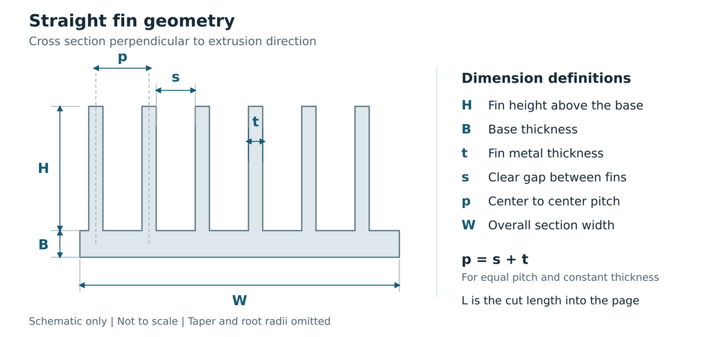
Fin height H runs from the top of the base to the fin tip. Base thickness B is separate, so the total section height is H + B. Fin thickness t is the metal width; clear gap s is the open space between adjacent fins. For equally spaced fins of constant thickness, center-to-center pitch p equals s + t.
For example, a 2 mm fin with a 6 mm clear gap has an 8 mm pitch. Calling both dimensions “spacing” would leave a 2 mm ambiguity in the drawing. With tapered fins, identify the height where thickness and gap are measured, and show the minimum passage explicitly.
Natural convection needs an open path
For a conventional vertical plate-fin arrangement, leave a path for cooler air to enter below and warmer air to leave above. An enclosure wall, shelf or cable bundle can obstruct that path even when the profile itself has generous gaps.
Closely packed fins can restrict buoyancy-driven flow. ATS discusses this trade-off in its natural-convection fin-spacing guidance. Use candidate geometries appropriate to the available height, temperature difference and orientation, then compare them in the enclosure. There is no single gap dimension that establishes the optimum for every passive heat sink.
Forced convection needs pressure as well as flow
Use the fan pressure-flow curve together with the resistance of the complete air path. The free-air flow rating alone does not show how much air will pass through a fin array behind a filter, grille and enclosure opening. Oriental Motor explains how obstructions increase pressure loss and reduce delivered flow.
Check that air enters the channels and can leave them. A bypass gap around the sink or recirculation from the outlet to the inlet can weaken cooling. Compare candidates using the intended fan and duct arrangement, rather than assigning the same velocity to every profile without checking how it is produced.
Taller fins add geometric area, but temperature is not uniform along a real fin. The useful benefit depends on conduction through the fin and heat removal at its surfaces. Dense or tall profiles therefore need thermal and airflow evaluation together.
Size the Base Around the Heat Source Layout
The base must distribute heat from the device footprint into the fin field. A small source near one edge creates a different spreading problem from a large centered module. Mark every source location and its individual losses on the drawing; total watts alone leave that layout unresolved.
Base thickness is a variable to compare, rather than a fixed percentage of fin height. ATS’s spreading-resistance analysis illustrates why improving heat spreading can compete with the fin area available inside a fixed overall height.
For example, within a hypothetical 40 mm height envelope, increasing the base from 3 mm to 5 mm reduces the available fin height from 37 mm to 35 mm. Whether that change helps depends on the source footprint, material and cooling conditions. These dimensions illustrate the trade-off and are not a recommended profile.
Compare temperature at the critical source locations, not only an average base temperature. For several devices, evaluate their simultaneous operating combinations and local temperature limits. Keep mounting stiffness, thread engagement and any material removed by machining in the same review.
Specify the alloy and temper used in calculations and quotations. Both 6063 and 6061 occur in commercial extrusion ranges. Our heat sink material selection guide covers their roles and the wider material trade-offs without treating an alloy name as a finished-part performance rating.
Review Extrusion Feasibility Before Releasing a Die
A feasible profile depends on the complete section, material, tooling and tolerances. Alucad’s design guidance specifically cautions against applying one minimum fin thickness or maximum fin height to every extrusion. A capability quoted for another section should therefore be treated as a discussion point, not automatic approval of a new drawing.
Ask the extruder to review the proposed fin roots and tips, narrow channels, wall transitions and overall balance of the cross-section. The Aluminum Extruders Council recommends attention to symmetry, wall-thickness transitions and rounded corners to improve process efficiency, while recognizing that some applications require more complex shapes.
Use that review to separate dimensions that are functionally critical from those that can tolerate adjustment. A small change in an unconstrained fin or corner may be preferable to tightening the entire drawing. Agree any design change before using the revised geometry in thermal comparisons.
Define the aspect ratio before comparing limits
“Fin aspect ratio” is not sufficiently precise on its own. ATS describes a ratio of fin height to the distance between fins, while Alucad also discusses fin height relative to thickness. Those are different relationships.
For a hypothetical 30 mm fin, 6 mm gap and 2 mm thickness, height divided by gap is 5, while height divided by thickness is 15. State the numerator, denominator and measurement location when requesting a feasibility review. Neither number independently proves that the profile can be extruded.
Specify the Interface and Finished Part Together
A drawing should show how the heat source contacts the base, how the assembly is clamped and which surfaces are inspected after machining and finishing. Identify datum features, contact-face flatness and surface requirements, mounting holes, thread depths and access for the assembly tools.
Thermal interface materials reduce the effect of microscopic air gaps, but installed resistance depends on the contact area, material and assembly conditions. Select the interface and mounting load together with the device’s mechanical limits. A thick gap-filling pad should not be substituted for a thin interface without revisiting the thermal budget.
Keep the inspection method consistent with the drawing. A dimensional check of overall thickness does not establish contact-face flatness, and a single indicator reading does not establish the condition across the whole surface. Define where and how a critical characteristic is measured.
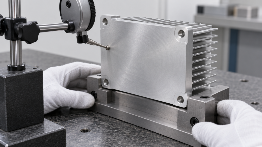
Specify the surface treatment and any masked or subsequently machined areas. Confirm how the finish affects mating dimensions, contact surfaces and electrical requirements. Do not assume that an attractive finish establishes a cooling improvement or an electrical-insulation rating.
Validate the Candidate in the Intended Enclosure
Use calculations and, where needed, simulation to narrow the choices before testing. Include the actual source layout, interface assumptions, mounting arrangement and air path. A simulation result is only useful if its boundary conditions represent the assembly being evaluated. TI’s thermal guide distinguishes simplified networks from models that capture multiple heat paths.
Plan the prototype test around a decision. For the illustrative 100 W project, the primary question is whether the defined case location remains within the 85°C design target at the specified inlet condition. A low average heat sink temperature would not answer that question by itself.
| Test condition to control | Evidence to record |
|---|---|
| Heat load and operating mode | Loss estimate or measured heat input, duty cycle and stabilization criterion |
| Air entering the heat sink | Inlet temperature, enclosure configuration and installation orientation |
| Fan and air path | Fan setting, supply condition, duct configuration and relevant flow data |
| Mechanical interface | TIM grade, installed condition and repeatable mounting procedure |
| Temperature measurement | Sensor location, attachment method, instrument setup and uncertainty |
Repeat the relevant operating conditions after changing the profile, interface or mounting procedure. For an infrared measurement on metal, account for surface emissivity and reflected surroundings; TI highlights emissivity correction when measuring metal package surfaces.
If a prototype is machined from billet, document differences from the planned extrusion: alloy, fin taper, root geometry, finish and contact surface. A useful fit prototype does not automatically qualify the production process. Before release, connect the approved drawing revision to representative parts and the test evidence used for acceptance.
If the candidate misses the target, locate the limiting part of the heat path. Revisit the interface, spreading and available air before increasing fin density. When practical extrusion geometry cannot meet the requirement, discuss another fin construction, a heat-spreading assembly or a different cooling architecture. That decision should follow the limiting condition rather than a fixed wattage cutoff.
Prepare an Extruded Heat Sink Design Brief for HJTC
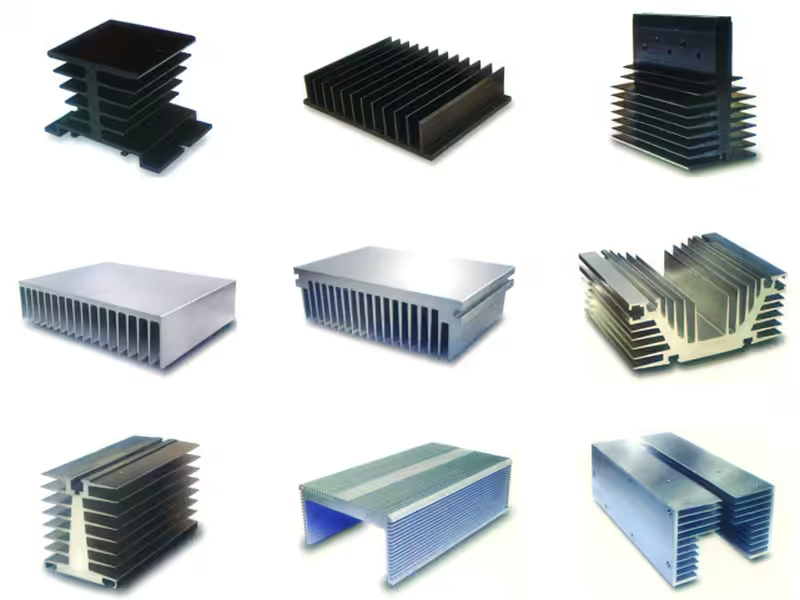
HJTC’s extruded aluminum heat sink range groups AL6063 profiles into compact, standard, high-density, large and special-profile categories. These provide starting points for different space, airflow and structural requirements. The published product page emphasizes reviewing the heat-source footprint, available envelope, airflow and mounting before profile selection.
For an initial discussion, send a cross-section, finished length and assembly view. Mark the contact areas and any features that must remain fixed. Include:
- The heat entering each contact area, operating combinations and peak durations.
- The temperature limit, its measurement reference, intended margin and inlet-air condition.
- Overall space, allowed mass, mounting details and the proposed interface material.
- Installation orientation, enclosure layout and fan information when applicable.
- Alloy or finish constraints, critical dimensions and required inspection evidence.
- Prototype quantity, anticipated production quantity and the acceptance test to be used.
If the geometry is still open, explain which requirement drives the project. For example, a fixed enclosure height and an existing fan constrain the design differently from a requirement for passive operation. If an existing prototype runs too hot, include its operating conditions and sensor locations so that its measurements can inform the next revision.
Discuss Your Extruded Heat Sink Design with HJTC
Share your drawing and operating conditions to begin reviewing a suitable profile and finished-part requirements.
Frequently Asked Questions
What is the best fin spacing for an extruded heat sink
It depends on cooling mode, geometry, orientation and the available air path. Compare clear gap and pitch explicitly, then evaluate the candidate under its actual natural or forced convection conditions. A spacing value without those conditions is incomplete.
Does a thicker base always improve cooling
No. It can help distribute heat from a concentrated source, but it also adds mass and uses part of the height envelope. Compare the resulting source temperatures with the fin geometry and airflow held to the intended design constraints.
Can one extrusion profile be used at different lengths
Yes, a continuous profile can be cut to different lengths. Confirm the thermal performance of each finished length under its relevant source and airflow conditions; a length change should not be treated as an automatic proportional change in thermal resistance or allowable heat load.
Is a custom extrusion die always necessary
No. Start by checking whether an existing profile can satisfy the thermal and assembly requirements after practical cutting and machining. Compare a new die when the available sections leave important requirements unmet or create excessive finishing work.
What is needed before approving production
An agreed finished-part drawing, resolved extrusion and machining requirements, and representative thermal and dimensional evidence. Keep the material, interface, finish, mounting procedure and tested operating conditions connected to that approval.