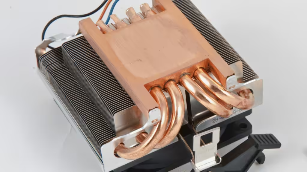
Heat sinks transfer heat by conduction from a component into a base and fins. Convection carries energy from those surfaces into moving air, while radiation exchanges heat with surrounding surfaces. Cooling performance depends on the complete path, including the thermal interface, fin geometry and airflow.
Understanding heat sink heat transfer helps you ask a more useful design question: where does the largest temperature rise occur, and which change can reduce it? A more conductive metal, a larger fin stack and a faster fan address different parts of that problem.
This guide follows heat from an electronic component to its surroundings, explains the three mechanisms, and gives a practical method for reviewing a prototype with HJTC.

The Heat Path from a Component to Its Surroundings
A heat sink is a thermally connected structure that helps move heat away from a device. Its fins expose additional surface area to the cooling environment.
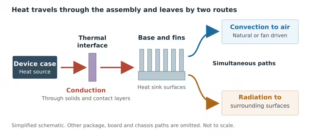
For a typical component with a heat sink mounted on its case, follow these stages:
- Heat travels from the active region of the device through its package.
- It crosses the contact between the case and the heat sink, usually through a thermal interface material.
- The base spreads heat toward the fins, which conduct it along their surfaces.
- The exposed surfaces exchange heat with air by convection and with surrounding surfaces by radiation.
The last two mechanisms can operate at the same time. Radiation is not a step that heat must pass through after convection.

Actual electronics can also transfer heat into the circuit board, mounting hardware or chassis. This simplified path helps organize the discussion, but a system model must include other significant paths.
Conduction through the Interface Base and Fins
Conduction moves heat through the solids and contact layers between the source and the cooling surfaces. Thermal conductivity describes a material’s ability to conduct heat, but the length and cross-section of the path also matter.
The thermal interface and mounting contact
Two apparently flat surfaces still contain microscopic gaps. A thermal interface material, or TIM, helps replace air in those gaps and reduce contact resistance. Its installed performance depends on the material, contact area, bond-line thickness and mounting conditions.
Specify the interface as part of the assembly. A paste intended for a thin bond line and a compliant pad intended to bridge a gap serve different mechanical needs. Review the actual gap and the allowable component load before selecting either. The aim is a suitable, repeatable contact condition; greater clamping force is not automatically acceptable.
For a prototype, record the TIM grade, application method, assembled thickness where relevant, and mounting procedure. A comparison becomes difficult to interpret if the interface changes at the same time as the heat sink.
Heat spreading inside the metal
Heat from a small source must spread through the base before it can reach more distant fins. The base therefore performs a different role from the fin surfaces that release heat to the environment.
Ask whether the proposed structure delivers heat to the available area effectively. If the hottest region remains concentrated near the source, review source placement, base geometry and possible spreading solutions. If the base is relatively uniform but sits far above the inlet-air temperature, the air-side path deserves attention. These observations guide further measurement; they do not establish the cause on their own.
Material selection belongs in this review, alongside geometry and manufacturing constraints. Preserve the alloy and temper in the drawing so that thermal assumptions remain connected to the part being quoted.
Convection from the Fins to the Air
Convection combines heat transfer at the surface with the transport of energy by moving fluid. In an air-cooled assembly, the air must reach the fins, absorb heat and leave the heated region.
Natural convection
Natural convection is driven by buoyancy. Air warmed near the heat sink can rise while cooler air replaces it. The available circulation depends on the geometry and installation orientation.
Closely packed fins provide more area, but narrow passages can make it harder for air to move through them. ATS discusses this trade-off in its natural-convection fin-spacing guidance. A fin arrangement that performs well with a fan should therefore be evaluated separately before it is used without one.
Specify the installed orientation and the nearby obstructions. Include the enclosure in the evaluation: a heat sink on an open bench may have a circulation path that disappears when the lid and surrounding components are fitted.
Forced convection
A fan or blower drives air through the cooling arrangement. Its installed flow depends on the resistance of that arrangement. The fan’s free-air flow rating describes a condition with no opposing static pressure, so it is not the airflow automatically delivered through a fin stack, filter and grille.
For straight-fin designs, review how air enters the channels and where it exits. Also check for routes that let air bypass the useful surfaces. Fan selection and duct design should be discussed together, using the operating condition that the assembled product can actually achieve.
| Design question | Natural convection | Forced convection |
|---|---|---|
| What drives the air | Buoyancy | Fan or blower pressure |
| What installation detail matters | Orientation and room for circulation | The complete inlet, channel and outlet path |
| What should be checked about fins | Spacing that permits circulation | Area, channel resistance and available airflow together |
| Which test conditions should be recorded | Orientation, enclosure and ambient conditions | Installed fan setting, airflow conditions and inlet temperature |
Use the air temperature entering the heat sink as a reference. Room temperature alone may miss heating caused by upstream components or recirculated exhaust.
Radiation to Surrounding Surfaces
A warm heat sink also emits thermal radiation and absorbs radiation from its surroundings. Net radiative heat transfer depends on the temperatures, emissivity and geometric relationship of the surfaces involved. Air motion is not required for this mechanism.
Surface treatment can change emissivity. Anodizing may make radiation more significant, especially in natural-convection or low-airflow conditions. Its contribution must be evaluated for the actual assembly; there is no universal percentage of heat that every heat sink removes by radiation.
An enclosed heat sink exchanges radiation with the surfaces it can see, including enclosure walls and neighboring components. Those surfaces may be warmer than the air entering the product. Using room temperature for every radiation boundary can therefore misrepresent the system.
Convection and radiation are simultaneous paths from the heat sink surface. If they exchange heat with boundaries at the same temperature, their effective thermal resistances can be represented in parallel. If those boundary temperatures differ, retain the separate temperature nodes in the model. Do not add their resistances as though the same heat must pass through both in sequence.
Connecting Heat Transfer to Thermal Resistance
Thermal conductivity is a material property, usually reported in W/m·K. Thermal resistance describes a defined heat-transfer path, in K/W or °C/W. For a given steady-state heat flow:
Temperature rise = heat flow × thermal resistance
The resistance must belong to the path and conditions being analyzed. Package, interface and heat-sink resistances can form a useful first approximation when most heat follows that route. A package’s published junction-to-ambient value already describes a specified test configuration; it should not simply be added to separate case, interface and heat-sink terms.
A worked example showing which change matters
Consider a hypothetical 60 W device, with incoming air and radiative surroundings both at 35°C. Assume steady state and that all significant device heat follows the modeled package-to-heat-sink path. The values below are selected for illustration, not taken from an HJTC product test.
| Resistance in the model | Baseline | Lower interface resistance | Lower sink resistance |
|---|---|---|---|
| Junction to case | 0.20 K/W | 0.20 K/W | 0.20 K/W |
| Case to heat sink | 0.10 K/W | 0.05 K/W | 0.10 K/W |
| Heat sink to environment | 0.70 K/W | 0.70 K/W | 0.45 K/W |
| Total resistance | 1.00 K/W | 0.95 K/W | 0.75 K/W |
| Calculated junction temperature | 95°C | 92°C | 80°C |
For the baseline, the calculation is 35 + 60 × 1.00 = 95°C. Reducing interface resistance by 0.05 K/W lowers the calculated temperature by 3°C. Reducing sink-to-environment resistance by 0.25 K/W lowers it by 15°C.
The larger improvement comes from the larger reduction in total resistance. This does not establish that airflow changes are always preferable to interface changes. It shows why a design review should estimate the resistance that can realistically be removed from each part of the path.
Here, sink-to-environment resistance represents the complete sink performance under the assumed conditions, including its surface heat rejection. Do not add a separate radiation resistance on top of a measured sink rating that already includes that effect. Real heat sinks also vary with temperature and airflow, so treat the fixed values as a local sensitivity example.
What to Check When Cooling Falls Short
Temperature observations are most useful when they are paired with a defined heat load and reference temperature. The following table is a diagnostic starting point derived from the heat-path model, not a set of guaranteed fault diagnoses.
| Observation | Possible explanation to investigate | Useful next check |
|---|---|---|
| Hot component with a much cooler base | Interface, mounting or package-path resistance | Verify sensor locations, contact, TIM and assembly load |
| Hot base with a large rise above inlet air | Limited surface heat rejection | Measure inlet conditions and inspect the actual air path |
| Higher temperatures after closing the enclosure | Restricted circulation or warmer inlet air | Repeat measurements with the final lid, vents and surroundings |
| Little improvement after adding a fan | Bypass, insufficient installed flow or a different limiting path | Compare temperatures along the path and verify fan operating conditions |
| Strong temperature concentration near the source | Spreading or uneven cooling | Record source size, base temperatures and airflow distribution |
Avoid changing several variables in the same trial. A controlled sequence might first repeat the mounting process, then compare two fan settings, and then examine a geometry change. Keep the electrical operating point and measurement method consistent, and wait for the defined steady condition before comparing results.
A brief test record should include the drawing revision, heat load, sensor locations, inlet temperature, orientation, fan settings and assembly procedure. Record the enclosure configuration as well. These details allow a later design revision to be compared with the correct baseline.
For pulsed or short-duration loads, add a time history. Thermal mass can influence warm-up behavior, but a cooler temperature early in a test does not by itself establish better steady-state heat rejection.
Applying the Heat Path to an HJTC Project
At HJTC, our thermal product scope includes heat sinks, liquid cold plates and industrial aluminum profiles. We connect thermal requirements with manufacturability, supporting project discussions from development through production planning.
For an air-cooled design, our extruded aluminum heat sink category is a starting point for discussing a continuous fin profile, mounting features and secondary machining. Begin with the actual heat path and available airflow so that the profile can be evaluated in context.
Prepare these inputs for the discussion:
- Heat-source dimensions, locations and the heat entering the cooling assembly.
- Sustained and peak heat loads, including the duration of transient conditions.
- Component temperature limits and the relevant case or junction reference.
- Available space, mounting points, contact surfaces and the proposed TIM.
- Incoming air temperature, installation orientation, fan information and enclosure layout.
- Prototype quantity, expected production quantity and the intended verification method.
For a power-conversion product, distinguish rated electrical output from the losses that become heat. For multiple devices sharing a heat sink, identify each source and its location instead of supplying only one aggregate wattage.
If air cooling cannot meet the requirement within the available space and operating constraints, a liquid cold plate may be a route to evaluate. That discussion also needs the coolant inlet condition, flow, pressure requirements and the rest of the cooling loop. Changing the architecture changes the boundary conditions; it does not remove the need to define them.
Discuss Your Heat Sink Design with HJTC
Send your drawing, thermal load and airflow conditions to start a discussion about the structure and verification your project needs.
Frequently Asked Questions
Does a heat sink work without a fan
Yes. A suitable passive design can reject heat through natural convection and radiation. It must be evaluated with the intended heat load, orientation and enclosure. Removing the fan from an assembly designed for forced airflow changes its operating conditions.
Can an ordinary heat sink cool below the incoming air temperature
An assembly rejecting heat only to its incoming air needs a positive temperature difference to transfer that heat. A colder radiative surface, a colder liquid supply or refrigeration changes the problem. A fan alone does not provide a refrigerated boundary.
Does a hotter heat sink mean it is working badly
Not necessarily. Its temperature must be interpreted alongside device temperature, heat load and inlet conditions. A hot sink can indicate that heat reaches it effectively, or that heat rejection is limited. Measure the relevant temperature differences before drawing a conclusion.
Are more fins always better
No. Fins increase area, but spacing also affects air movement. Compare the complete geometry at the available airflow and orientation. An optimum spacing reported for one design should not be treated as a universal dimension.
Does radiation matter in an enclosed product
It can. Internal surfaces still exchange radiation with each other. The result depends on their temperatures, emissivity and geometric exposure, while the enclosure must ultimately reject the received heat through its own cooling paths.