
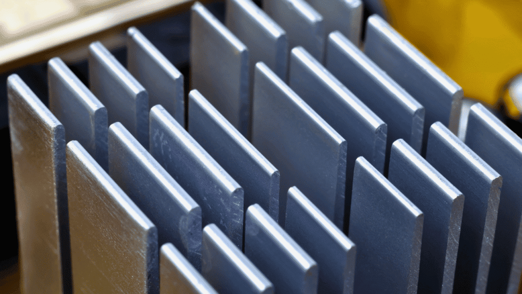
To choose an extruded heat sink, start with the heat that must leave the component, the allowable temperature rise and the air available at the fins. Use those inputs to set a thermal resistance target. Then shortlist profiles that fit the enclosure, support the mounting arrangement and can be manufactured at the required volume.
A profile drawing shows whether a part fits. A thermal performance curve shows how it behaved under particular test conditions. You need both, followed by validation in the intended assembly, to make a useful selection.
This guide takes engineers and purchasing teams through eight decisions, from the initial thermal budget to a quotation that includes machining, finishing and inspection.

Extruded Heat Sink Selection at a Glance
| Step | Decision | What you should have before moving on |
|---|---|---|
| 1 | Establish the thermal requirement | Heat load, temperature limits and a sink-to-air resistance budget |
| 2 | Define the available envelope | Dimensioned space, heat-source locations and installation orientation |
| 3 | Confirm the cooling conditions | Natural convection requirements or a realistic forced-air operating point |
| 4 | Screen fin and base geometry | Candidate profiles with suitable channels, base thickness and manufacturability |
| 5 | Specify material and finish | Alloy, temper, surface treatment and contact-area requirements |
| 6 | Choose an existing or custom profile | A justified tooling and secondary-machining route |
| 7 | Define mounting and inspection | A controlled drawing with measurable acceptance criteria |
| 8 | Validate and compare quotations | Assembly test results and a complete production cost breakdown |
If you need a process introduction first, read our overview of extruded heat sinks.
1. Calculate the Required Thermal Resistance
Start with heat dissipation, rather than the equipment’s nameplate power. A converter’s output power and the losses entering its heat sink are different quantities. For several components, record each device’s loss, contact area and location instead of providing only a board-level total.
Use the air temperature entering the heat sink. Air inside an enclosure may already have been heated by upstream components.
For a steady-state, single-source design with a specified case-temperature limit and a dominant heat path through the sink, an initial budget is:
RθSA ≤ (TC,limit − TA,inlet) / Q − RθCS
- RθSA: resistance from the heat sink base at the source location to inlet air, in °C/W.
- RθCS: case-to-sink interface resistance, including the installed interface and its contacts.
- Q: heat passing into the heat sink, in watts.
- TC,limit: the applicable case-temperature design limit.
- TA,inlet: the air temperature approaching the heat sink.
Worked example: a 120 W heat load
The following values are illustrative design inputs, not measured HJTC product data.
| Input | Example value |
|---|---|
| Heat entering the heat sink | 120 W |
| Case-temperature design limit | 95°C |
| Inlet air temperature | 45°C |
| Installed case-to-sink interface resistance | 0.10°C/W |
RθSA ≤ (95 − 45) / 120 − 0.10 ≈ 0.317°C/W
That is the calculated ceiling before a design margin is allocated. Suppose the project selects 0.25°C/W as its initial screening target. Under the same simplified assumptions:
TC = 45 + 120 × (0.10 + 0.25) = 87°C
The resulting 8°C margin belongs to this example; it is not a universal recommendation. Allocate margin for the application’s ambient variation, fan tolerance, interface condition and service environment.
When the requirement is a junction-temperature limit, use the device manufacturer’s applicable package model and cooling surface. Do not substitute a datasheet junction-to-ambient value for the heat sink’s resistance. TI’s semiconductor thermal metrics guidance explains these distinctions. Multiple heat sources, significant PCB heat paths and short power pulses require a model beyond this simple series calculation.
2. Define the Envelope and Installation Direction
An extruded profile has a constant cross-section before secondary machining. Its cut length is a separate dimension. Use a marked drawing so the supplier knows which dimension follows the extrusion direction.
Record the available width, overall height and length, together with space for screws, clips, cables, nearby components and airflow. A heat sink that occupies the entire mechanical envelope can leave too little room for its installation or air path.
For a conventional flat-base profile:
Overall height = base thickness + fin height
Keep the heat-source footprint separate from the heat sink footprint. A small device near one edge of a wide base presents a different spreading problem from a centrally mounted device covering most of that base.
For natural convection, identify the product’s installed orientation and provide a path for air to rise through the channels. For forced air, mark the intended flow direction through the fins. Check the actual orientation inside the enclosure, including any service positions that must remain operational.
3. Match the Profile to Real Airflow
Natural convection
A passive heat sink relies on buoyancy-driven airflow and radiation. Fin spacing, orientation, nearby walls and inlet and outlet clearance all matter. Closely packed fins can restrict the air movement needed to use their additional surface area.
There is no single fin gap that suits every passive extrusion. Screen the spacing against fin height, channel length, temperature rise and the installed environment. A profile tested upright in open air needs further assessment inside a compact enclosure.
Forced convection
Use the fan’s pressure-flow curve together with the resistance of the complete air path. The free-air CFM rating does not tell you how much air passes through an installed heat sink.
Filters, grilles, adjacent boards and the fins themselves affect the operating point. Air may also bypass the fins through easier paths. ATS’s explanation of fan and system curves provides useful background for this check.
When requesting performance data, ask for:
- Air velocity at a defined location, or flow rate with a defined duct arrangement.
- Pressure drop at the stated flow condition.
- Fan model, speed or control condition when a fan is part of the tested assembly.
- Heat-source size and position, cut length, orientation and temperature measurement points.
Read the conditions beneath the thermal resistance value
A lower published °C/W value is useful only when the comparison conditions are relevant. A result at a higher air velocity cannot establish which profile will perform better with your fan.
Also check the tested length. For example, Wakefield Thermal’s thermal extrusion catalog identifies thermal resistance values based on a 3-inch length in natural convection, alongside longer stock lengths available for purchase. The stock length and the thermal test length are separate pieces of information.
Changing cut length requires a fresh performance assessment; do not scale the resistance in direct proportion to length.
4. Balance Fin Geometry and Base Thickness
Use the following checks to narrow the profile shortlist.
| Feature | Selection question |
|---|---|
| Fin gap | Can the available airflow pass through the channels at acceptable pressure drop? |
| Fin height | Does added height improve useful heat transfer within the enclosure clearance? |
| Fin thickness | Can the fins conduct heat effectively and remain practical to extrude and handle? |
| Base thickness | Is heat spreading adequate for the source footprint without unnecessary mass or loss of fin height? |
| Profile width | Can the base and airflow make effective use of the outer fins? |
| Cut length | What performance data applies to the actual length and channel arrangement? |
Define aspect ratio before discussing limits
In this guide, fin-channel aspect ratio means fin height divided by the clear gap between adjacent fins. State that definition on the drawing or quotation request, because other ratios describe different geometric constraints.
No single aspect-ratio limit, minimum fin thickness or maximum width applies to every extrusion supplier and profile. Alloy, die design, section complexity, tolerances and process capability must be reviewed together. Request feasibility confirmation for the complete cross-section before releasing tooling.
Check whether the base is using the fin area
A small heat source on a much wider base can produce a substantial temperature gradient. Increasing base thickness may improve spreading, but it adds mass and can reduce available fin height when overall height is fixed.
Compare source-area and base temperatures during simulation or testing. If the source region remains hot while distant fins contribute little, investigate spreading and interface resistance before adding more fins. The objective is a lower source temperature within the allowed envelope.
5. Specify the Alloy, Temper and Surface Finish
6063 aluminum is a common starting point for extruded heat sinks, supported by its suitability for extrusion and surface finishing. The final material specification should also identify the temper and any mechanical requirements.
If the part carries significant structural loads or needs extensive fabrication, compare alternatives with the supplier. For thermal calculations, use properties for the selected alloy, temper and operating temperature rather than assigning a pure-aluminum conductivity value to every aluminum part.
Treat the surface finish as part of the functional specification:
| Area or requirement | What to confirm |
|---|---|
| Exposed fins and external surfaces | Corrosion environment, appearance and the intended coating or anodizing condition |
| Thermal contact area | Surface condition used in the interface design; masking or post-finish machining if required |
| Grounding or bonding point | The required electrical contact and how it will be achieved |
| Threads and locating features | Final dimensions and acceptance after finishing |
Anodizing can increase the surface’s ability to emit thermal radiation. That contribution is generally more significant in passive cooling than in effective forced-air cooling. Specify the actual finish and validate the assembly; color alone does not establish a cooling improvement.
6. Decide Between an Existing and a Custom Profile
Start by asking whether an available cross-section can meet the thermal and mechanical requirements. Confirm its availability, material and condition rather than assuming that an item pictured in a catalog is stocked.
| Route | When to assess it | What to include in the quotation |
|---|---|---|
| Existing profile, cut to length | Cross-section and base already suit the application | Material availability, cut tolerance, finish, minimum order and delivery |
| Existing profile with machining | Fins are suitable but holes, slots or contact features need adjustment | Machining stock, setup, removed material and final inspection |
| Custom extrusion | Existing sections cannot meet the required geometry or integration | Die development, trials, approval samples, machining and production terms |
A new die becomes more compelling when the cross-section will be reused and it can incorporate useful features. The Aluminum Extruders Council describes profiles that also serve as enclosures or mounting surfaces. Compare those possibilities with the machining and assembly work they may replace.
Changing cut length or adding a hole pattern may leave the underlying die unchanged. Changing the cross-section requires a separate feasibility review. Our aluminum profile solutions provide a starting point for discussing that geometry.
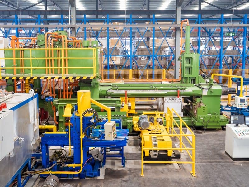
HJTC’s manufacturing reference material includes extrusion equipment, surface treatment and finished heat sink profiles. When requesting a quote, define the condition you are buying: an unfinished profile, a machined component or a finished, inspected part. Each requires a different quotation scope.
7. Specify Mounting, Machining and Inspection Together
The thermal interface and mounting arrangement belong in the first drawing review. Select the thermal interface material together with the contact area, installed thickness, pressure and any electrical isolation requirement.
Define the features that control the assembly:
- Contact surface location, flatness, surface finish and machining allowance.
- Hole positions, thread sizes and usable thread depths.
- Datums used to inspect the mounting features.
- Fastener or clip arrangement and the applicable assembly load or torque.
- Deburring, cleanliness and protection of contact surfaces and fins.
Apply tight tolerances where they serve a function. Requesting the same precision on every fin and every non-contact surface can add cost without solving the assembly’s critical problem.
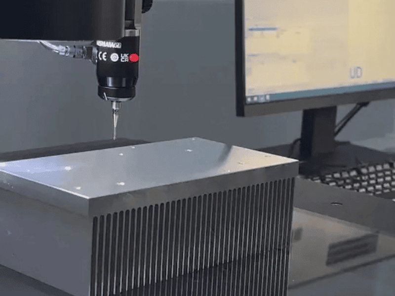
Checking the base and mounting features helps turn a profile into a controlled component. The inspection example below shows a probe positioned over a heat sink base. Use the drawing and acceptance record to state which features must be measured, their limits and the inspection method.
8. Validate the Assembly and Compare Complete Quotes
Use representative samples with the intended interface material, mounting procedure, fan arrangement and enclosure. Test the worst relevant sustained load and ambient condition, and assess transient operation separately where it matters.
Record component temperatures and heat sink inlet temperature. For forced-air designs, also record fan conditions and relevant airflow or pressure measurements. Recheck the conditions that could change during service, such as filter loading, installation orientation or interface aging.
An aggregation-router example in HJTC’s application material identifies extruded heat sinks at FPGA and SFP28 positions, with different cooling constructions at the CPU and switching chip. The selection lesson is to review each source and its air path individually. A suitable extrusion at one position does not establish suitability across the board.
For procurement, compare the finished accepted part. Separate die and fixture charges, material, cutting, machining, finish, inspection, packaging and logistics. Ask for prototype and repeat-order pricing against the same drawing revision, with minimum order requirements and timing stated explicitly.
A lower profile price can lose its advantage when extensive machining, a different interface arrangement or additional assembly work is included.
When Should You Consider Another Cooling Construction?
Revisit extrusion when the required profile is impractical to manufacture, the available air cannot remove the heat, or base spreading remains a major limitation.
| Unresolved constraint | Alternative to evaluate |
|---|---|
| Required fin geometry is outside a practical extrusion proposal | Skived or bonded-fin construction |
| Heat must spread from a small source or reach a remote fin area | A heat-pipe or vapor-chamber assembly |
| Air cooling cannot meet temperature and acoustic requirements in the available space | Liquid cooling, assessed with the complete coolant loop |
Use our skived vs. extruded heat sink comparison for the manufacturing trade-off. If liquid cooling becomes a candidate, review the liquid cold plate options together with flow, pressure drop, coolant and system integration requirements.
Extruded Heat Sink RFQ Checklist
Send one consistent requirement set to every supplier. If a parameter is unknown, label it as an item for engineering review rather than assigning an unsupported value.
| Information to send | Useful detail |
|---|---|
| Application and operating environment | Equipment type, duty cycle, enclosure and service conditions |
| Heat sources | Loss per device, contact dimensions, locations and load combinations |
| Temperature limits | Case or junction limit, measurement location and required margin |
| Air conditions | Inlet temperature, orientation, fan curve, ducting and flow data if available |
| Mechanical envelope | Marked width, overall height, cut length and installation clearances |
| Material and finish | Alloy, temper, coating and any masked areas |
| Interface and mounting | TIM, installed thickness, contact pressure and fastener arrangement |
| Manufacturing drawing | STEP model plus a dimensioned drawing with revision and tolerances |
| Acceptance requirements | Critical dimensions, inspection records and thermal validation conditions |
| Purchasing plan | Prototype quantity, order quantity, forecast and requested delivery dates |
Use this checklist when reviewing HJTC’s custom heat sink solutions or requesting a profile recommendation.
Frequently Asked Questions
How do I choose the right extruded heat sink size?
Set a thermal resistance target, define the installation envelope and check candidate performance under relevant airflow conditions. Width, cut length and overall height are starting dimensions; source location, base spreading and mounting clearance also affect the selection.
How many watts can an extruded heat sink dissipate?
There is no useful universal wattage limit. For a defined steady-state condition, heat dissipation depends on the permitted temperature rise and total resistance along the relevant heat path. A watt rating needs its temperature, airflow and mounting conditions to be meaningful.
Is a high-density profile always better?
No. Additional fins increase area but narrow the flow passages. Compare candidates with the intended fan and air path, or under the correct natural-convection conditions, before accepting a denser profile.
Can one extrusion be used at several cut lengths?
Often, if the same cross-section fits each assembly. Confirm machining and mounting for each version, and evaluate thermal performance at the actual length. A shared die does not make the different lengths thermally equivalent.
Should I choose an existing profile or order a custom die?
Assess an existing profile first when it can meet the requirement with reasonable secondary work. Consider a custom die when the geometry, mounting integration or repeat-production economics justify development and qualification.
Request an Extruded Heat Sink Selection Review
Share your heat load, temperature limit, inlet air conditions and available space with HJTC. Include a STEP model or dimensioned sketch, mounting requirements and expected quantities.
These inputs let us discuss whether an existing profile, a machined extrusion or another cooling construction is worth taking into sample validation.