
Choose extruded heat sinks when an available or manufacturable aluminum profile meets your temperature and size limits at an acceptable production cost. Consider skived heat sinks when you need thinner fins, a denser fin arrangement, or copper construction within a restricted space. In both cases, verify performance under the airflow and mounting conditions your product will actually have.
The manufacturing process shapes your design options. It does not, by itself, determine how much heat the finished assembly can remove.
For engineers and purchasing teams comparing skived vs. extruded heat sinks, the useful question is: which design meets the thermal target, fits the product, and remains practical to manufacture throughout its production life?
The server and telecom application examples below show how this decision works at the component and assembly level. Their value is in the documented design choices and operating conditions, which help make a more useful comparison than process labels alone.
Skived vs. Extruded Heat Sinks at a Glance
| Selection factor | Extruded heat sinks | Skived heat sinks |
|---|---|---|
| Manufacturing method | Heated metal is pushed through a die to form a continuous profile | Thin layers are cut and raised from a solid metal blank to form fins |
| Common material options | Aluminum alloys, including 6063 | Aluminum or copper |
| Base-to-fin construction | Integral base and fins in a conventional one-piece extrusion | Integral base and fins in a conventional skived design |
| Fin geometry | Limited by the complete profile and extrusion feasibility | Useful for thin, closely spaced fins beyond what a practical extrusion may allow |
| Tooling considerations | Existing profiles may avoid a new die; custom profiles require die development | No extrusion die for the fin pattern, but cutting tools, fixtures and setup are still required |
| Production economics | Often attractive for repeat orders using a stable profile | Depends on cutting time, material, tooling wear and finishing requirements |
| Airflow suitability | Can be designed for natural or forced convection | Can be designed for either; dense fin arrangements need particular airflow attention |
| Main selection question | Can a practical profile meet the requirement economically? | Does the additional geometry or material flexibility solve a specific thermal constraint? |
These are process tendencies. Final dimensions, tolerances, lead times and prices require a drawing review and a project-specific quotation.
How Each Manufacturing Process Works
Extruded heat sinks
Extrusion produces a long section with a consistent cross-section. The profile is cut to length and can receive secondary machining for mounting holes, pockets, component contact surfaces and other features.
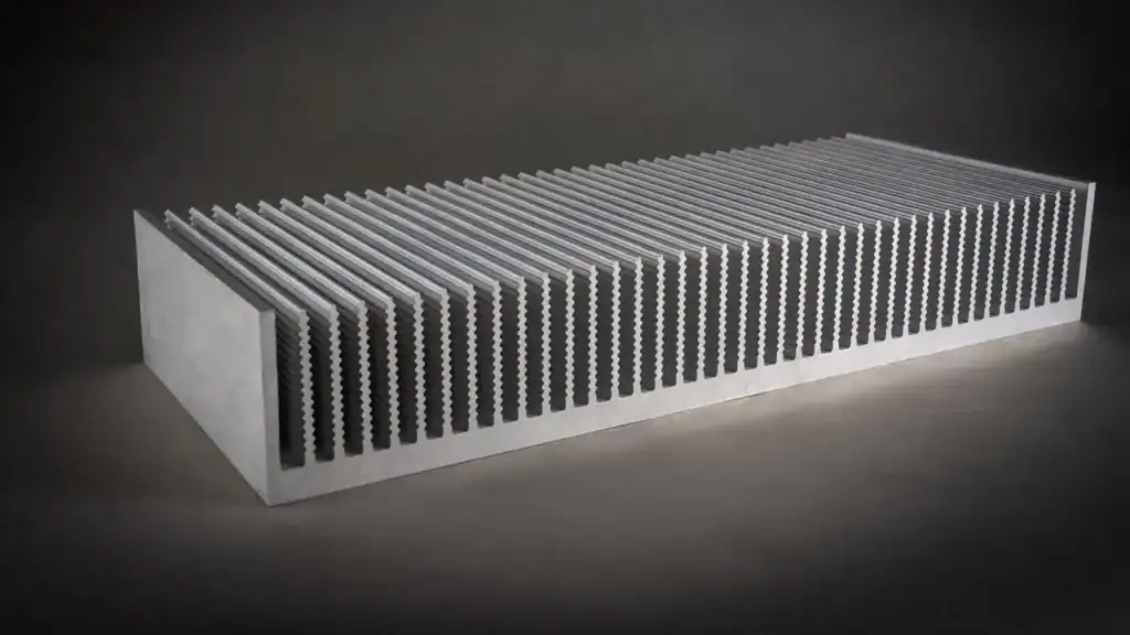
This makes extrusion worth considering when the same basic fin-and-base profile can serve a product family. Different lengths or hole patterns may be possible without changing the extrusion die, provided the original cross-section remains suitable.
Before designing a custom profile, check whether an existing one can meet the requirement. Our guide to how extruded heat sinks are made and used explains the process and common design considerations.
Application example: extrusion within an aggregation router. An air-cooled aggregation-router application sheet explicitly identifies extruded heat sinks for the FPGA and SFP28 positions. The same sheet identifies a vapor-chamber cooler for the switching chip and a heat-pipe cooler for the CPU.
Selection lesson: evaluate extrusion for each component’s requirements. Several cooling constructions can serve different devices within one product.
Skived heat sinks
Skiving uses a cutting tool to slice and lift layers from a metal blank while leaving each fin attached to the base. It is a useful manufacturing route for closely spaced fins in aluminum or copper.
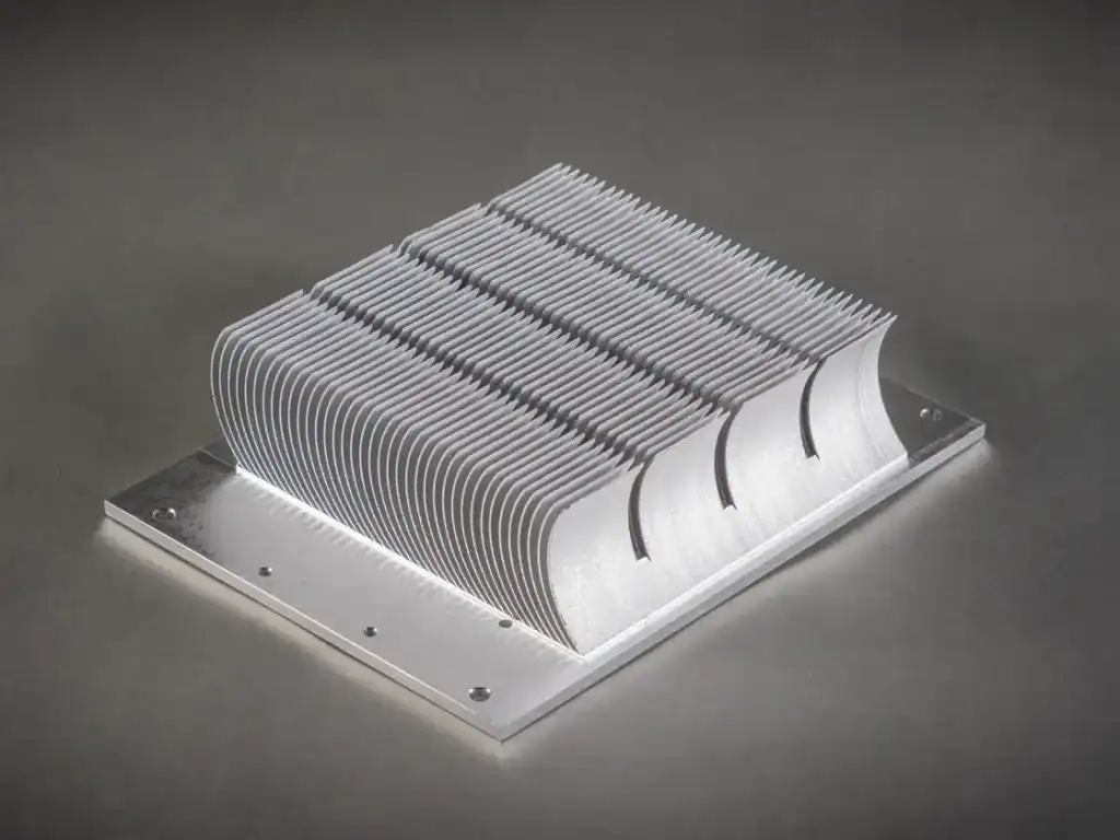
The potential benefit is greater freedom to create a particular fin arrangement. That benefit matters only when the arrangement improves the finished cooling system. Specify fin thickness, spacing, height and handling requirements together, and have the supplier confirm what is feasible for the selected material.
Application example: skived and extruded parts in one layout. A separate communications-equipment application layout identifies both skived and extruded heat sinks, alongside heat-pipe and vapor-chamber assemblies, at different locations in the enclosure.
For a similar product, compare the local heat sources, mounting space and airflow available at each position. The enclosure can accommodate more than one manufacturing process; each choice should have its own thermal and mechanical justification.
What Actually Determines Thermal Performance?
Fin density must match the available airflow
More fin area can help heat transfer, but tighter passages also affect airflow resistance. With a fixed fan, changing the heat sink changes the system resistance and can change the delivered flow.
Compare candidates in the same enclosure, using the intended fan and control setting, while recording airflow and pressure drop. A comparison at equal air velocity answers a different question: it may require different fan effort for each design. Fan and system performance curves help explain that distinction.
For passive cooling, assess fin spacing and installation orientation specifically for natural convection. Do not carry a dense forced-air design into a fanless product without checking its performance.
What two documented telecom assemblies show
The company application material includes two TH4 cooling assemblies with the same listed heat-source size and power, but different geometries and cooling arrangements:
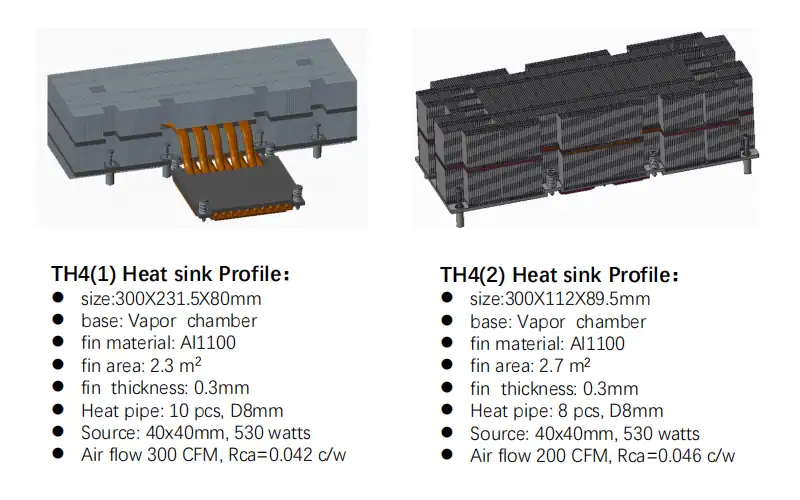
| Parameter reported in the application sheet | TH4(1) assembly | TH4(2) assembly |
|---|---|---|
| Overall dimensions, in the source’s stated order | 300 × 231.5 × 80 mm | 300 × 112 × 89.5 mm |
| Heat source | 40 × 40 mm; 530 W | 40 × 40 mm; 530 W |
| Base / fin material | Vapor chamber / AL1100 fins | Vapor chamber / AL1100 fins |
| Heat pipes | 10, diameter 8 mm | 8, diameter 8 mm |
| Fin area | 2.3 m² | 2.7 m² |
| Reported airflow | 300 CFM | 200 CFM |
| Thermal resistance, labelled Rca in the source | 0.042°C/W | 0.046°C/W |
These are reported application values. The sheet does not specify the complete test method or identify the fin-forming process. It also does not define the Rca measurement locations, so confirm that definition before comparing these figures with an Rsa design budget.
Selection lesson: fin area alone cannot rank these assemblies. Their airflow, dimensions and heat-pipe arrangements differ, and the larger listed fin area accompanies the higher reported resistance. The data supports comparing complete cooling arrangements under defined conditions; it does not isolate the effect of extrusion or skiving.
Material and heat spreading matter alongside the fins
Copper generally conducts heat better than common aluminum heat sink alloys, but it also adds weight and material cost. Its value depends on whether conduction and heat spreading are important limitations in the proposed design.
To identify that limitation, compare temperatures at the device contact area and across the base. Ask whether changing base thickness or material makes better use of the available fin area. A material change alone does not establish the performance of the complete assembly.
In a supplier comparison, separate two questions: what changes because of the manufacturing process, and what changes because one proposal uses copper while the other uses aluminum?
Both processes can provide an integral base and fins
Conventional one-piece extruded and skived heat sinks both avoid a separate bonded joint between the base and fins. Describing the absence of a fin-to-base bond as an advantage unique to skiving gives a misleading comparison.
There is still a separate interface between the electronic device and the heat sink. Review the thermal interface material options, contact area, flatness and mounting pressure as part of the assembly design.
When comparing samples, use the same approved interface material and mounting procedure. Otherwise, the measured difference may partly reflect the installation rather than the heat sink geometry.
Set a Thermal Target Before Choosing the Process
Start with allowable temperatures and actual heat dissipation. A product’s electrical power rating is not necessarily the heat load that reaches its heat sink.
Here is an illustrative steady-state calculation for a device whose cooling requirement is specified at its case. Assume that 100 W passes through the case-to-sink interface into the heat sink:
| Design input | Illustrative value |
|---|---|
| Heat entering the heat sink, Q | 100 W |
| Design case-temperature limit, Tc | 90°C |
| Air temperature entering the heat sink, Ta | 40°C |
| Case-to-sink interface resistance, Rcs | 0.10°C/W |
The initial maximum sink-to-air thermal resistance is:
Rsa ≤ (Tc − Ta) / Q − Rcs
Rsa ≤ (90 − 40) / 100 − 0.10 = 0.40°C/W
These inputs are an example, not HJTC product specifications or test results. Select a design with appropriate margin below this limit and validate it in the enclosure.
The calculation assumes a dominant heat path through the heat sink. For packages with significant heat flow through the PCB, multiple heat sources or transient loads, use the device manufacturer’s applicable thermal model. TI’s guide to semiconductor thermal metrics explains why package thermal parameters need careful interpretation.
Use our heat sink design guide to organize the thermal, mechanical and manufacturing requirements before requesting candidate designs.
Compare Total Manufacturing Cost
A useful quotation should separate the initial investment from recurring part cost. Request both options against the same material requirements, finish, inspection criteria, packaging and delivery quantity.
For an extruded option, identify whether the proposal uses an existing profile or a new die. Request any minimum order, die charges, sample approval steps and secondary machining costs separately.
For a skived option, ask how the requested fin geometry affects processing time, inspection and packaging. Confirm which design changes would require new fixtures or a fresh setup.
Use a purchasing comparison such as:
Program cost = tooling and setup + delivered unit cost × quantity + validation cost
Define the quotation boundary consistently. For example, specify whether the delivered unit price includes machining, finishing, inspection and protective packaging.
Request prices at prototype quantity, initial production quantity and expected annual demand. The cheapest sample does not establish the cheapest production route, and a lower piece price may require an initial investment that your actual volume cannot justify.
Lead time also needs a project-specific answer. Compare the dates for drawing approval, tooling or setup, first samples and repeat orders instead of relying on a universal lead-time claim for either process.
A Practical Selection Workflow
Use the following sequence to turn the comparison into a purchasing decision:
- Define the pass criteria. Record heat load, allowable temperatures, incoming air temperature, envelope and weight limit.
- Create an extrusion baseline. Ask whether an available or feasible custom profile can meet those criteria.
- State the reason to evaluate skiving. Identify the constraint it should address: fin geometry, material, available space or a combination of these.
- Compare complete assemblies. Include the fan, interface, mounting hardware and necessary ducting in each proposal.
- Validate shortlisted samples. Test representative operating conditions and document temperatures, airflow, noise and installation details.
- Release a controlled specification. Agree on drawings, critical dimensions, inspection criteria and the process for approving changes.
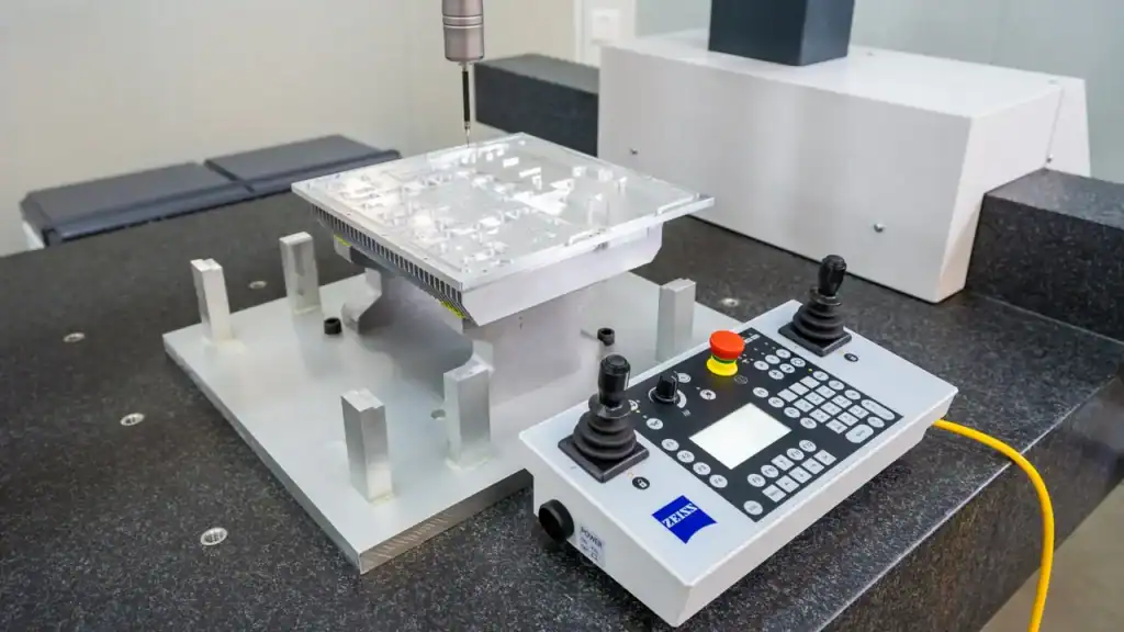
Application example: include the fan and acoustic requirements. A cooling-module application sheet lists heat sink structural design, fan development and matching, thermal simulation, and acoustic analysis. It also shows a noise-test setup. This provides a useful model for a comparison brief: ask for temperature and noise results for the intended assembly, including its fan operating setting.
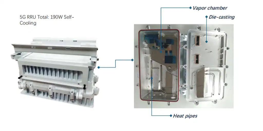
Application example: a 190 W RRU uses a combined cooling approach. A 5G remote radio unit example is labelled 190 W and described as self-cooled. Its construction identifies die casting, a vapor chamber and heat pipes. This is a reminder to consider the complete heat path when a project needs more than a fin-profile change. The 190 W figure belongs to that application and provides no general changeover threshold between extrusion and skiving.
Our custom heat sink options provide a starting point for discussing different constructions. If neither candidate meets the requirement within the available space and airflow, expand the design review to other cooling approaches, including liquid cold plates where the product can accommodate a liquid cooling system.
What to Include in Your Heat Sink RFQ
Give the supplier enough information to compare the two processes on the same basis:
- Heat sources: device locations, contact footprints, expected heat dissipation and duty cycle.
- Temperature requirements: device limits, maximum incoming air temperature and required design margin.
- Mechanical envelope: CAD files, available dimensions, keep-out areas, mounting orientation and weight limit.
- Airflow: passive or forced cooling, fan model, control setting, ducting, filters and noise constraints.
- Assembly interface: contact surfaces, mounting method, allowable clamping load, interface material and electrical isolation requirements.
- Manufacturing requirements: material, finish, critical tolerances, inspection needs, prototype quantity and annual demand.
Ask each proposal to explain the basis of its thermal estimate and any assumptions that still need validation. For a reported resistance value, request the measurement locations, heat-source footprint, airflow conditions, interface configuration and whether the result comes from simulation or physical testing. This makes it easier to compare a stock extrusion, a custom extrusion and a skived design without confusing a quoted capability with demonstrated performance.
Frequently Asked Questions
Are skived heat sinks always better than extruded heat sinks?
No. Skiving can make useful fin geometries and copper constructions practical, but the complete design must still meet its thermal target under the available airflow. An extruded design that passes the same requirements may be the better purchasing choice.
Can extruded heat sinks handle high power?
There is no single wattage limit that applies to the entire manufacturing process. Evaluate a specific design using heat load, source size, allowable temperature rise and cooling conditions. Request performance data under conditions representative of your product.
Do extruded heat sinks have a bonded joint between the fins and base?
A conventional one-piece extruded heat sink does not. Its base and fins form an integral profile, as the fins and base also do in a conventional skived heat sink. Bonded-fin assemblies are a different construction.
Which process is better for a prototype?
First check whether a suitable existing extrusion is available. It may avoid new die development. Skiving is another route worth quoting when the prototype needs a fin pattern that existing profiles cannot provide. Compare actual availability, setup cost and sample timing.
Should I specify copper before requesting a quotation?
Specify copper if the project already requires it. Otherwise, state the temperature, size and weight targets and request a justified material recommendation. This leaves room to compare the value of material changes alongside changes to geometry and airflow.
Discuss Your Heat Sink Requirements with HJTC
Send your drawing, heat load, temperature limits, cooling conditions and expected quantity through our heat sink project inquiry form. Ask for a comparison of feasible extruded and skived options, with the assumptions, manufacturing requirements and validation steps stated clearly.