
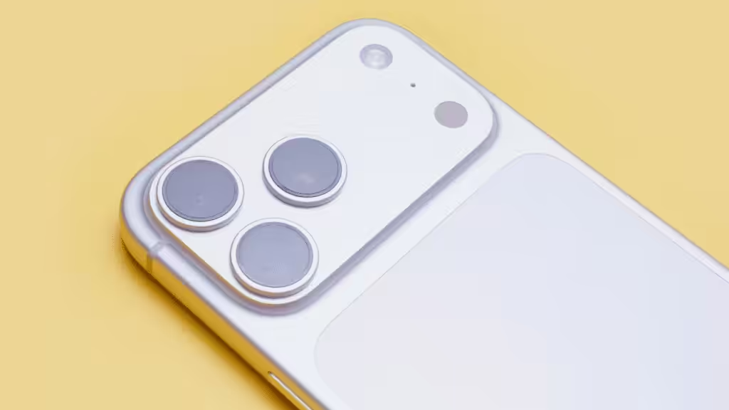
The iPhone 18 Pro vapor chamber is part of Apple’s redesigned cooling system for the A20 Pro chip. Apple confirms that both Pro models use the technology, with a larger heat-spreading structure and revised chip packaging intended to support sustained performance. A vapor chamber moves heat across a sealed component through evaporation and condensation; the surrounding structure still has to release that heat.
For users, the question is whether the phone can maintain performance during demanding work. For engineers, the interesting part is how the chip, thermal interface, heat spreader and enclosure work together within a limited space.
This guide separates Apple’s published specifications from general vapor-chamber engineering, then uses a reference from HJTC’s cooling materials to explain the design principles at a different scale.
Technical information checked on September 29, 2026.
What Has Apple Confirmed About the iPhone 18 Pro Vapor Chamber?
Apple’s iPhone 18 Pro product page describes the following changes relative to iPhone 17 Pro:
| Published change | How to interpret it |
|---|---|
| Three times the vapor-chamber surface area | A larger spreading structure; not a promise of three times the cooling capacity |
| More thermally conductive materials | A change to the thermal assembly; the complete material stack is not specified on the product page |
| Up to 40% better sustained performance | Apple’s claim for the combined chip and thermal design; not a 40% reduction in temperature |
The launch announcement also describes A20 Pro packaging that places memory beside the silicon die, allowing a more direct path between the processor and vapor chamber.
These are product-design statements and manufacturer performance claims. A controlled comparison of the vapor chamber alone would require matched heat sources, power, interfaces and cooling conditions.
How Does Vapor Chamber Cooling Work?
A vapor chamber is a sealed, usually thin heat spreader containing a working fluid and a porous wick. Instead of relying entirely on heat conduction through solid metal, it uses the fluid’s change of phase to redistribute energy.
The cycle has four stages:
- Heat enters near the processor. Liquid in the hot region absorbs energy and evaporates.
- Vapor travels through the internal cavity. It carries that energy toward cooler regions.
- The vapor condenses. Heat passes into the cooler chamber walls and the surrounding thermal structure.
- The wick returns liquid. Capillary action draws the liquid back toward the heat-input region, allowing the cycle to continue.
Advanced Cooling Technologies describes this operating principle. It explains why vapor chambers are useful when a small hot area needs access to a much larger cooling surface.
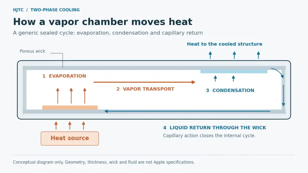
The diagram shows a generic working principle. It does not reproduce Apple’s internal geometry, wick design or fluid specification.
What Changed from iPhone 17 Pro?
The iPhone 17 Pro already used a vapor chamber. Apple’s 2025 announcement described a water-filled chamber integrated into the aluminum chassis.
For iPhone 18 Pro, the relevant changes are the larger spreading area and the revised thermal path from the chip. The engineering implication is that increasing spreader size and improving access to it can address different thermal bottlenecks.
A larger spreader cannot make full use of its area if heat encounters excessive resistance before reaching it. Conversely, an excellent chip interface still needs an effective downstream route for heat to leave. This is the same system-level issue discussed in HJTC’s high heat flux cooling guide.
The thermal interface still matters
In its iPhone 18 Pro teardown, iFixit observed a compliant interface between the processor and cooling assembly. The team did not identify the material’s exact composition.
That observation adds useful context to the phrase “direct” thermal path: close coupling can still involve an interface layer. It should not be read as proof of bare metal-to-silicon contact.
In general, a thermal interface material helps replace insulating air gaps between mating surfaces, as Boyd’s TIM explanation describes. For a custom assembly, the appropriate thermal interface material depends on the gap, contact pressure, surfaces and electrical requirements.
Is the iPhone 18 Pro Vapor Chamber Made of Stainless Steel?
Apple’s technical specifications identify recycled steel in components that include the vapor-chamber chassis. This establishes the use of steel in that structure, but does not provide a complete alloy specification or identify every internal layer.
The broader question is why steel can be useful in a heat spreader when copper is such a familiar thermal material.
Vapor-chamber performance depends on more than the conductivity of its shell. Mechanical strength affects how thin the walls can be, how much room remains for vapor flow, and how well the component resists deformation. Boyd’s ultra-thin vapor-chamber overview explains how stainless steel can support thinner walls and structural integration.
That is a general design tradeoff, not evidence that every steel chamber outperforms every copper chamber. The wick, working fluid, internal space, heat-source geometry and interfaces must be evaluated together.
Will the Vapor Chamber Stop an iPhone from Getting Hot?
The cooling system still has to transfer the phone’s heat into its surroundings. Spreading heat can reduce a concentrated hotspot while making a wider area of the enclosure warm. Surface warmth alone therefore cannot establish the temperature of the chip or the quality of its cooling.
For users, a more useful question is whether performance remains consistent during the same task under the same conditions. Compare sustained frame rates or completion times alongside temperature, brightness, charging state and room conditions. A short benchmark peak tells a different story from a long gaming session.
Apple’s temperature guidance specifies an ambient operating range of 0–35°C (32–95°F). This is the temperature around the device, not a permitted CPU or enclosure-temperature range.
The same guidance explains that warmth can occur during demanding activities and that temperature protection remains active. If the phone displays a temperature warning, turn it off, move it away from direct sunlight to a cooler environment, and let it cool.
A vapor chamber does not remove those operating limits.
Vapor Chamber vs. Heat Pipe vs. Liquid Cold Plate
These technologies all help manage heat, but their roles differ.
| Technology | Typical role | How heat continues out of the system |
|---|---|---|
| Vapor chamber | Spreads a concentrated load across a broader, relatively flat area | Through the connected enclosure, fin structure or another cooled surface |
| Heat pipe | Transports heat along a defined route, often toward a remote cooling region | Through the attached heat sink or condenser region |
| Pumped liquid cold plate | Transfers heat into coolant flowing through internal passages | Through an external radiator, heat exchanger or facility cooling loop |
Boyd’s two-phase cooling guide explains the different geometries and applications of vapor chambers and heat pipes.
The sealed fluid inside a phone’s vapor chamber does not make it equivalent to a pumped server-cooling loop. HJTC’s liquid cold plates address that separate part of thermal system design. For a wider comparison, see our heat sink types and cooling methods guide.
An HJTC Reference: Why Source Area and Airflow Matter
HJTC’s server and communications cooling reference materials include a TH5 heat sink configuration combining a vapor-chamber base with an aluminum fin assembly.
| Reference parameter | Value stated in the material |
|---|---|
| Overall assembly size | 280 × 112 × 85 mm |
| Base | Vapor chamber |
| Fin material | AL1100 aluminum |
| Heat-source footprint | 40 × 40 mm |
| Heat load | 860 W |
| Airflow | 400 CFM |
These are industrial application reference values, not iPhone specifications or results from a new HJTC test performed for this article.
The source footprint is 4 × 4 cm, or 16 cm². Dividing the stated load by that area gives a nominal average source heat flux of:
860 W ÷ 16 cm² = 53.75 W/cm²
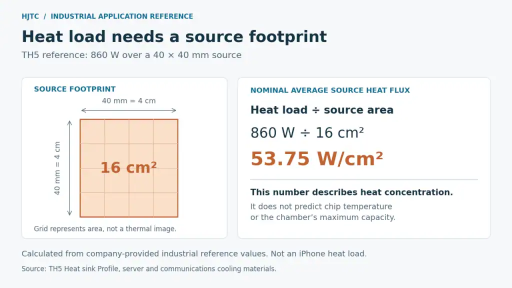
This calculation describes how concentrated the reference heat input is. It does not predict a chip temperature or establish the maximum capacity of a vapor chamber.
The reference also specifies airflow because spreading and heat rejection are separate tasks. The base distributes the load; the fin assembly and moving air carry heat onward. A different airflow condition would require a new evaluation of the complete assembly.
The same design questions apply to compact electronics, even though the scale is very different: How small is the source? Where can the heat spread? What removes it after it gets there?
What Engineers Should Specify for a Custom Cooling Design
A useful design brief starts with operating conditions, not simply a request for the biggest possible vapor chamber.
- Source map: Heat load, source dimensions, multiple hotspots and duty cycle.
- Temperature targets: Component limits, allowable enclosure temperature and worst-case ambient conditions.
- Mechanical constraints: Available footprint, height, mounting points and permitted contact load.
- Heat rejection: Chassis conduction, available airflow or coolant conditions.
- Validation: Representative workloads, operating orientations and repeatable measurement locations.
Record the interface stack as well as the spreader. A successful change must improve the temperature or sustained-performance target in the assembled product. Our heat sink design guide provides a starting point for organizing those inputs.
iPhone 18 Pro Vapor Chamber FAQs
Does iPhone 18 Pro Max also have a vapor chamber?
Yes. Apple’s launch information confirms the technology for both iPhone 18 Pro models.
Does “40% better sustained performance” mean 40% cooler?
No. Performance and temperature are different measurements. Apple’s figure describes the combined platform; it is not a stated temperature reduction attributable to the chamber alone.
Is a vapor chamber the same as a thermal pad?
No. A pad forms a conductive interface between surfaces. A vapor chamber uses a sealed two-phase process to spread heat. They can serve different roles within one assembly.
Does the vapor chamber guarantee longer battery life?
A cooling component by itself does not establish battery runtime. Power consumption, battery capacity, display settings, connectivity and workload also matter. Use a matched battery test to assess the complete phone.
Does the chamber need refilling?
No routine refilling is involved. The working fluid is sealed inside the component and circulates through its evaporation-and-condensation cycle.
Discuss a Custom Heat-Spreading Assembly with HJTC
If your project involves a compact controller, networking device, server or other electronic assembly, share the heat-source map, space constraints, interface requirements and available airflow or coolant conditions.
Explore HJTC’s custom heat sink solutions or send your thermal requirements to HJTC to discuss the appropriate combination of spreading, heat transport and final cooling.